Broadcast reception apparatus receiving broadcast by using directional antenna

Inactive Publication Date: 2009-11-24
FUNAI ELECTRIC CO LTD
View PDF23 Cites 5 Cited by
  • Summary
  • Abstract
  • Description
  • Claims
  • Application Information

AI Technical Summary

Benefits of technology

[0019]The present invention was made in view of the above-described circumstances, and an object of the present invention is to achieve further ensured safety in a broadcast reception apparatus receiving airwave through a variable directivity antenna.
[0023]Accordingly, a time from start of operation for power supply to the directional antenna until improper connection is eliminated as a result of detection or the like of improper connection in the broadcast reception apparatus can be made as short as possible. Therefore, improper connection between the broadcast reception apparatus and the directional antenna can be detected and eliminated in a short period of time from the start of operation for power supply to the directional antenna.
[0024]In this manner, further ensured safety is achieved in the broadcast reception apparatus receiving the airwave through the directional antenna.
[0027]Further, according to the present invention, in the broadcast reception apparatus, the timing at which power is supplied to the directional antenna is later than the timing of power supply to the output portion. Therefore, safety of the broadcast reception apparatus is further ensured.

Problems solved by technology

If connection is improper, however, power that should be supplied to the variable directivity antenna is returned to the broadcast reception apparatus, which may result in damage.

Method used


Image

  • Broadcast reception apparatus receiving broadcast by using directional antenna
  • Broadcast reception apparatus receiving broadcast by using directional antenna
  • Broadcast reception apparatus receiving broadcast by using directional antenna

Examples


Embodiment Construction

[0032]One embodiment of the broadcast reception apparatus according to the present invention will be described in detail with reference to the drawings. Though a smart antenna is adopted herein as an exemplary antenna, the directional antenna capable of changing an airwave reception direction in the present invention is not limited thereto. Any antenna of another type, that is, any directional antenna capable of switching a reception direction (Multi-Directional antenna), may be employed.

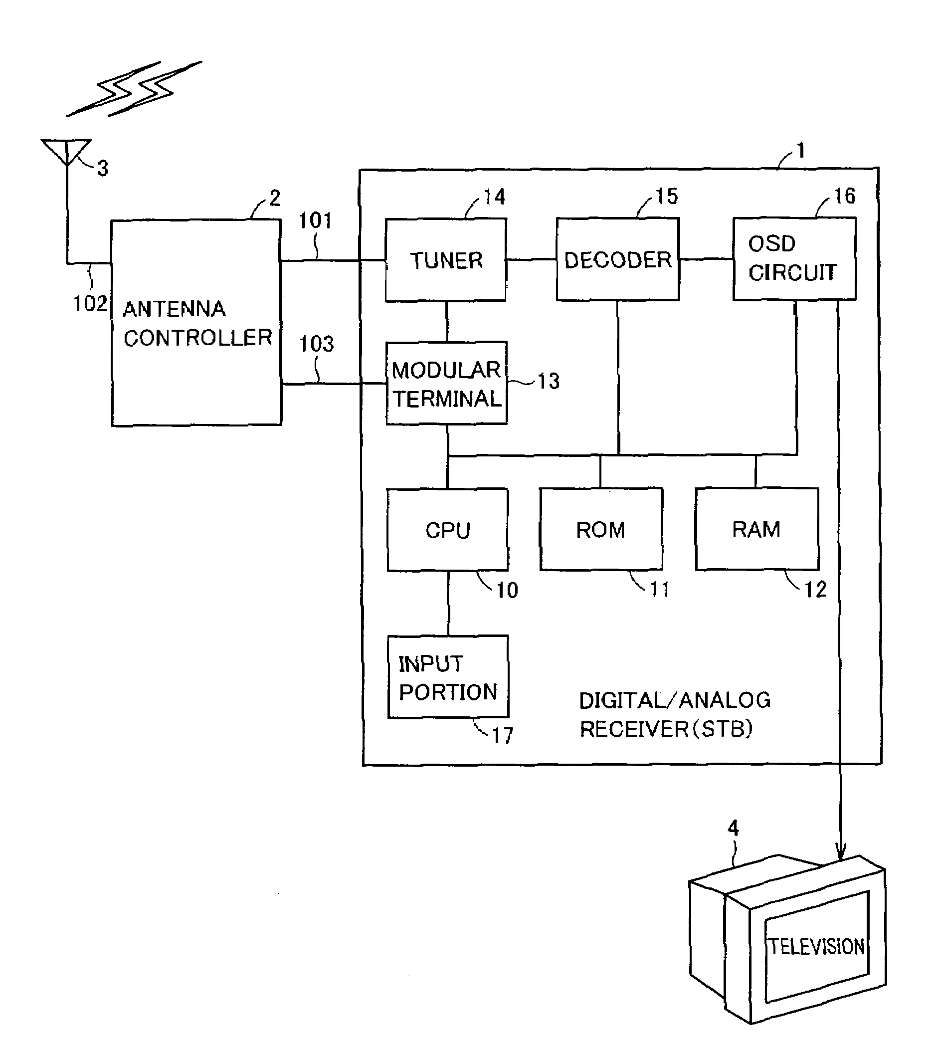
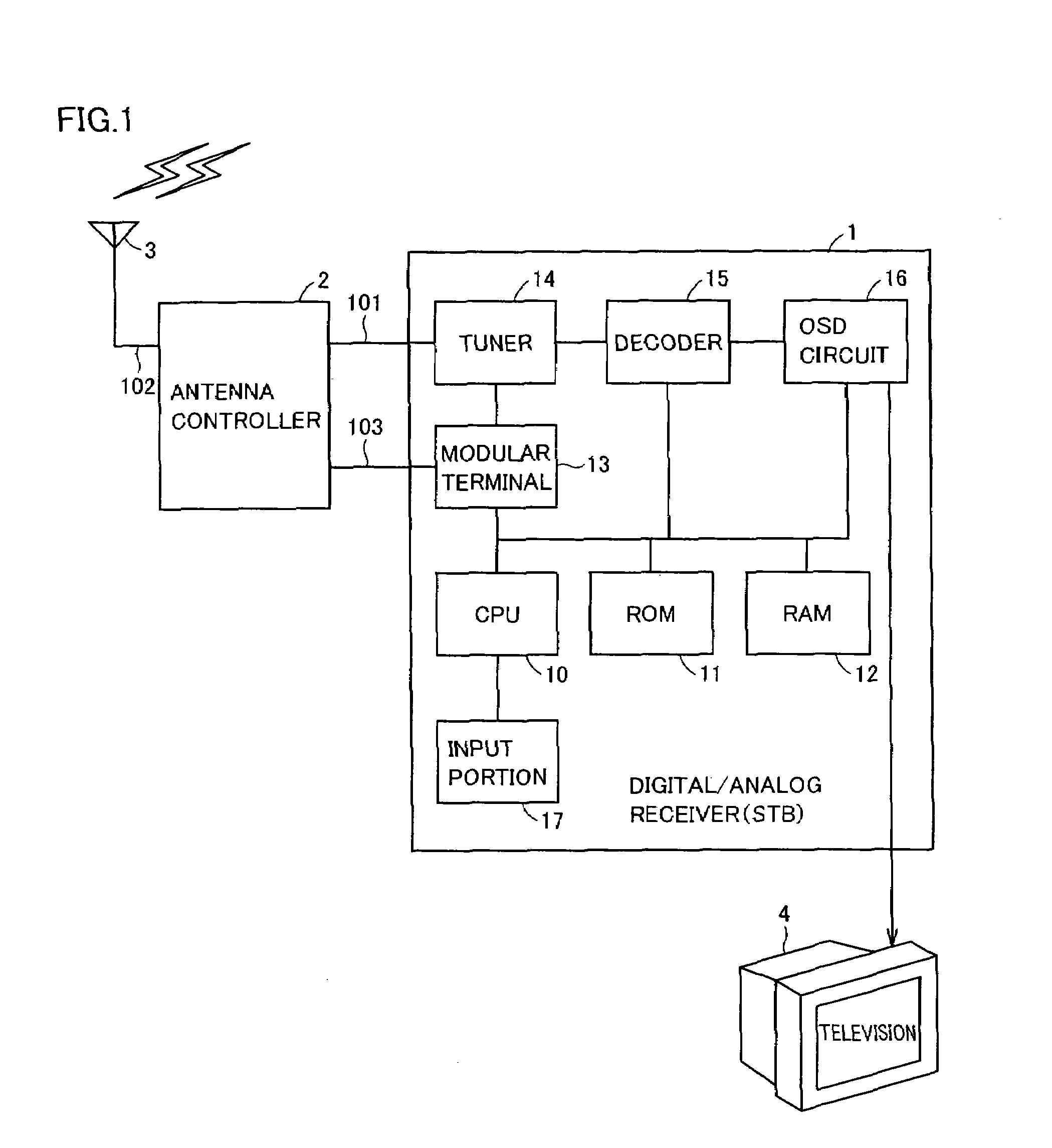
[0033]A configuration of a digital / analog receiver (hereinafter, abbreviated as “STB” (Set Top Box)) complying with EIA 909 standard representing one embodiment of the broadcast reception apparatus according to the present invention will be described with reference to FIG. 1.

[0034]STB 1 is connected to a smart antenna 3 through an antenna controller 2. The smart antenna refers to an antenna constituted of a plurality of antenna elements, capable of switching directivity by exciting each antenna elem...


PUM


Abstract

A broadcast reception apparatus is connected to a directional antenna capable of changing an airwave reception direction. The broadcast reception apparatus includes a tuner selecting a frequency of airwave received by the directional antenna. When a prescribed condition is satisfied, power is supplied to the tuner, and thereafter power is supplied to the directional antenna.

Description

BACKGROUND OF THE INVENTION[0001]1. Field of the Invention[0002]The present invention relates to a broadcast reception apparatus, and more particularly to a broadcast reception apparatus capable of receiving broadcast by using a directional antenna.[0003]2. Description of the Background Art[0004]Various techniques to cause a broadcast reception apparatus connected to an antenna for receiving airwave to carry out power ON / OFF control of the antenna have conventionally been disclosed. Such techniques are mainly directed to suppression of power consumption.[0005]For example, Japanese Patent Laying-Open No. 2003-283351 discloses a technique to start power feed to a converter of a reception antenna on condition that at least one receiver is turned on in an apparatus connected to a reception antenna and a plurality of receivers and distributing airwave received at the reception antenna to the plurality of receivers.[0006]In addition, Japanese Patent Laying-Open No. 2003-284063 discloses a...

Claims


Application Information

Patent Timeline
Patent Type & Authority Patents(United States)
IPC IPC(8): H04N7/20H04B1/18H04B7/10H04N5/44
CPCH04N21/4432H04N21/44209H04N5/63H04N5/4401H04N5/46H04N21/42638H04N21/426
Inventor ONOMATSU, TAKEHIRONARITA, SHUSUKE
Owner FUNAI ELECTRIC CO LTD
Why Eureka
Try Eureka