Cookware handle with metal insert and overmold

a technology of overmolding and cookware, applied in the field of cookware handles, can solve the problems of phenolic handles that can fail under extreme conditions, can be dangerous, and the handle is still susceptible to dangerous failures

Active Publication Date: 2009-12-01
ACCESS BUSINESS GRP INT LLC
View PDF59 Cites 25 Cited by
  • Summary
  • Abstract
  • Description
  • Claims
  • Application Information

AI Technical Summary

Benefits of technology

[0007]In another embodiment, the metal insert is configured to prevent movement of the overmold with respect to the insert. The metal insert may include a flat portion and a portion that is cured to match the shape of the overall cookware handle. The insert may also include a one or more notches extending through the insert. In this embodiment, the overmold extends around and through the notch to secure the overmold to the insert and prevent rotation of the overmold about the insert.
[0009]The phenolic overmold of the present invention provides a long-lasting, high-heat resistant cookware handle with reinforced strength. The overmold molded over the insert provides a long lasting, secure connection between the overmold and the insert. The shape and configuration of the insert prevent unwanted rotation or other movement of the overmold with respect to the insert. The attachment of the handle to a cookware vessel via the metal insert enables a secure connection of the handle to the cookware vessel, and the air gap created by the spacer reduces the heat transfer from the vessel to the handle.

Problems solved by technology

Unfortunately, even phenolic handles can fail under extreme conditions, such as direct contact with a gas flame.
These failures can be dangerous, especially if a handle breaks when the vessel is filled with extremely hot materials.
However, these handles are still susceptible to dangerous failures because the phenolic is not well secured to the screw and may rotate about the screw.
Other manufacturers have tried molding soft materials, like silicone rubber, over metal handles attached to a cookware vessel, but these soft materials do not last long and may not have the heat-resistant qualities of phenolic or other thermosetting polymers.

Method used


Image

  • Cookware handle with metal insert and overmold
  • Cookware handle with metal insert and overmold
  • Cookware handle with metal insert and overmold

Examples


Embodiment Construction

I. Overview

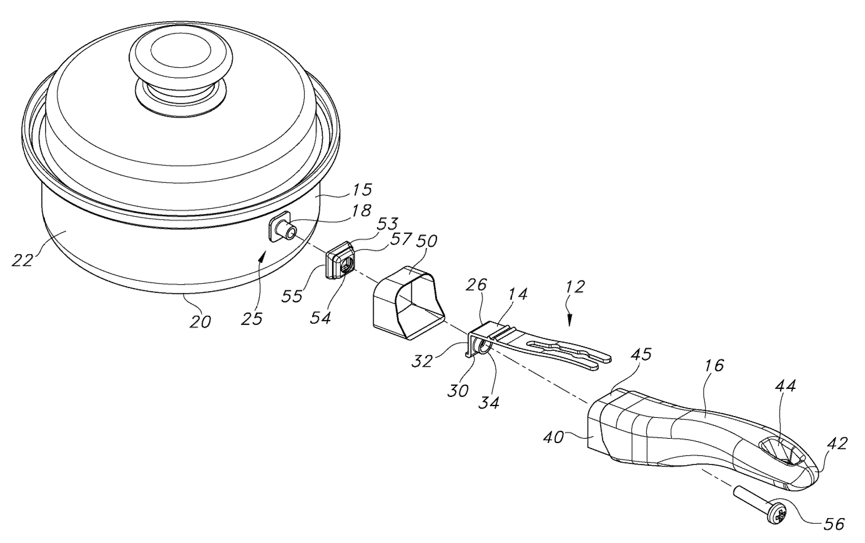
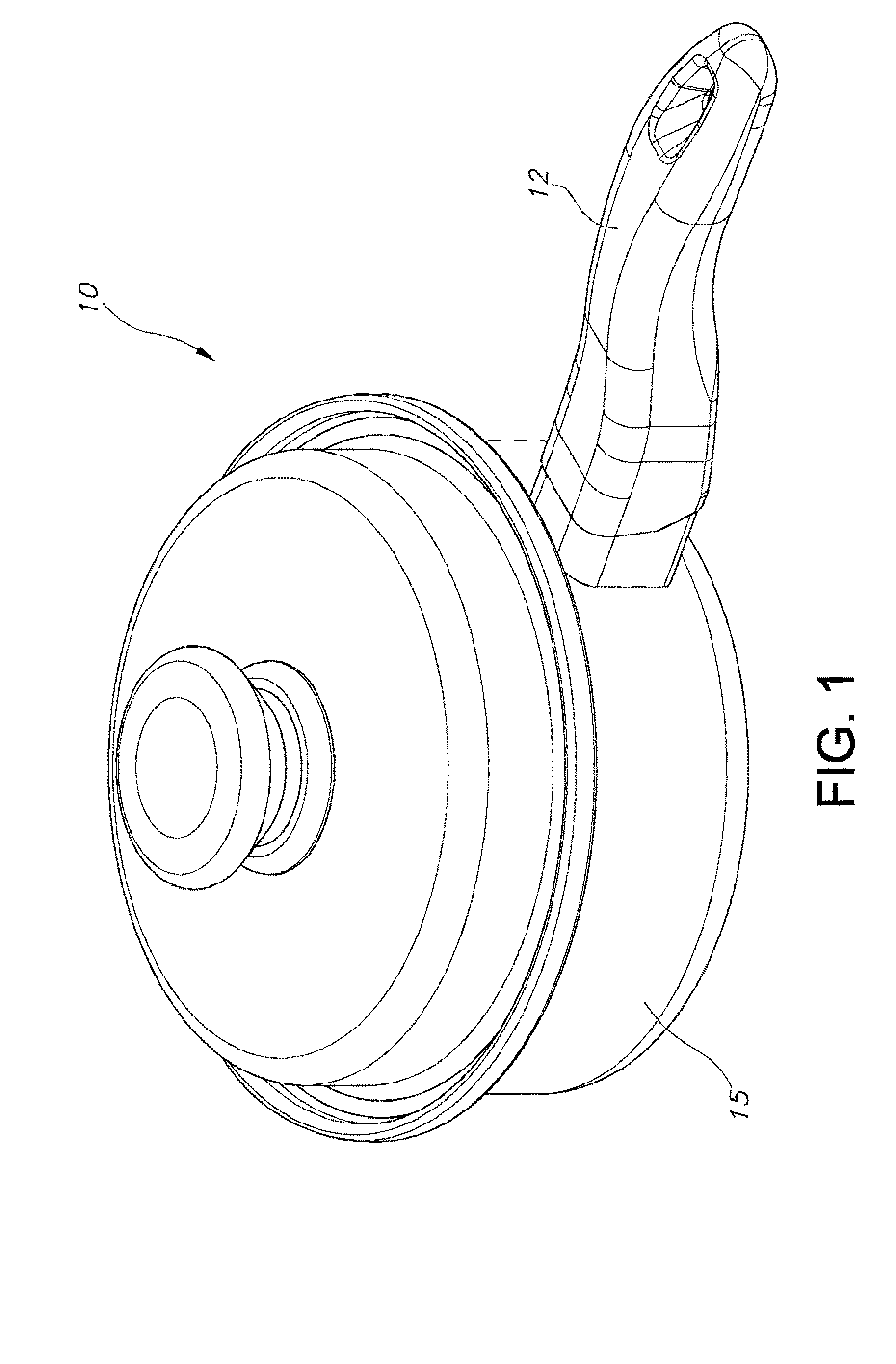
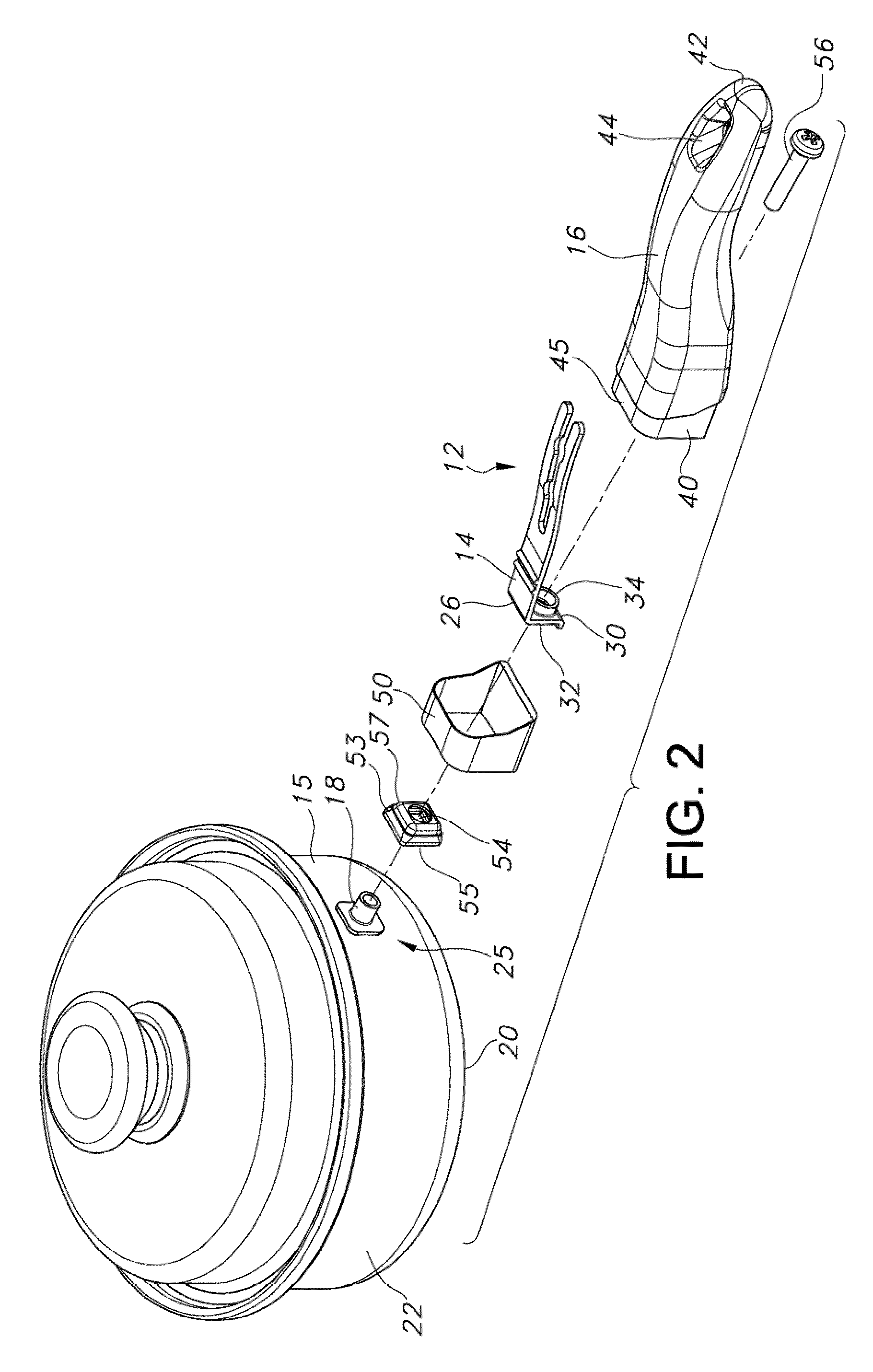
[0024]A article of cookware 10 including a cookware handle 12 according to one embodiment of the present invention is shown in FIG. 1. Shown in FIG. 2, the handle 12 generally includes a metal insert 14 and a cured phenolic overmold 16 molded over the metal insert 14. The metal insert 14 includes a screw boss 34 for connecting the handle 12 to the vessel 15.

II. Structure

[0025]For purposes of illustration, the present invention is shown and described in an embodiment where the vessel 15 is a conventional saucepan, however, the vessel may alternatively be any desired article of cookware, or another non-cookware vessel that requires a high-heat resistant, durable handle. As shown, the vessel 15 is manufactures of a conventional material, such as stainless steel, and includes a bottom 20 and a sidewall 22 extending from the bottom 20. The sidewall 22 of this embodiment includes at least one attachment point 25 for attaching the handle 12. As illustrates, the attachment point ...


PUM


Abstract

A cookware handle includes a metal insert and a cured phenolic overmold molded over the insert. The metal insert may be shaped to prevent movement of the overmold with respect to the insert, and may include a screw boss for attaching the handle to a cookware vessel. The overmold is molded over the insert into the shape of a handle. The overmold may encapsulate the insert, and may define a hole aligned with the screw boss to receive a screw that extends through the screw boss and into the cookware vessel. The present invention also includes a method for manufacturing a cookware handle, including the steps of a) providing a metal insert having an attachment portion; b) overmolding a phenolic molding material over the insert, the overmold shaped in the form of a cookware handle; and c) attaching the overmold and insert to a cookware vessel with the attachment portion of the insert.

Description

BACKGROUND OF THE INVENTION[0001]The present invention relates generally to cookware handles, and more particularly to a long-lasting, high-heat resistant cookware handle.[0002]Many different types of handles are known in the cookware industry for attachment to cookware vessels such as saucepans, frying-pans and the like. These handles must endure the rigorous kitchen environment, and enable the vessels to be gripped easily, even when hot. The best handles, therefore, are those with good thermal insulation properties and high durability.[0003]Cookware handles are often formed from a cured phenolic resin or another thermosetting polymer. Phenolic molding materials have high-heat resistant characteristics and are resistant to deterioration. Very commonly, these phenolic handles are solid, compression molded parts that attach to a cookware vessel, for instance, by a screw boss molded into the handle.[0004]Unfortunately, even phenolic handles can fail under extreme conditions, such as d...

Claims


Application Information

Patent Timeline
Patent Type & Authority Patents(United States)
IPC IPC(8): B65D25/28A47J36/00B25G1/10B25G1/12A47J27/00A47J37/10
CPCA47J45/061A47J45/08Y10T16/4707Y10S16/12Y10T16/466Y10S220/912A47J36/34
Inventor HOFF, SUSAN K.GOOD, RICK G.LI, KAM YUAN
Owner ACCESS BUSINESS GRP INT LLC
Why Eureka
Try Eureka