
Eureka
For R&D, Eureka makes reading and utilizing patents & technical documents easy.
Eureka AIR
Designed for self-driven R&D workflows. Generate viable solutions, solve complex R&D challenges, empower your innovation with AI.

Eureka Materials
Designed for material experts only. Revolutionize your material R&D, from search, analyze, to developing new materials.

TechResearch
Generate reliable direction feasibility study reports for your R&D in just a few steps.

TechSeek
Discover and master advanced knowledge NOW. Basics, ideas, possibilities, all at once.

TechMind
As an expert in R&D Theories, TechMind can generates customized viable solutions instantly.

TechRisk
Analyze your overall solution with one click, know your potential R&D risks in advance.

TechMonitor
Get weekly tech updates, stay abreast of the latest tech innovations and key insights.
Ultrasonic endocavity probe having adjustable length insert
- Summary
- Abstract
- Description
- Claims
- Application Information
AI Technical Summary
Problems solved by technology
Method used
Image

Examples
first embodiment
[0026]FIGS. 4A and 4B are illustrations showing an exemplary configuration of an ultrasonic probe according to the first embodiment of the present invention. As shown in FIG. 4A, an endocavity probe 1 is used as an example of the ultrasonic probe according to the first embodiment of the present invention. The endocavity probe 1 includes an insertion rod (as an example of an insertion member) 2, a handgrip (as an example of a holding portion) 3, a cable 4, and a fixer (or a fastener) 5. The insertion rod 2 includes an ultrasonic sensor 2a at its head (distal) end and is inserted into an endocavity of a specimen such as a patient P or an abject to be examined. The abdominal cavity is one example of an endocavity of the patient P. In one embodiment, the insertion rod 2 is sufficiently thin so as to reduce an incision size for the insertion of the insertion rod 2 in the abdominal cavity. This may help reduce patient's discomfort associated with the insertion. The ultrasonic sensor 2a ty...
second embodiment
[0039]FIGS. 6A and 6B are illustrations showing an exemplary configuration of an ultrasonic probe according to the second embodiment of the present invention. As shown in FIG. 6A, an endocavity probe 10 is used as an example of the ultrasonic probe according to the second embodiment of the present invention. The endocavity probe 10 includes an insertion rod (as an example of an insertion member) 11, a handgrip (as an example of a holding portion) 12, a cable 13, and a fixer (or a fastener) 14. The insertion rod 11 includes an ultrasonic sensor 11a at its head (distal) end and is inserted into an endocavity of the patient P. The abdominal cavity is one example part of an endocavity of the patient P. In one embodiment, the insertion rod 11 is sufficiently thin so as to reduce an incision size for the insertion of the insertion rod 11 in the abdominal cavity. This may help reduce patient's discomfort associated with the insertion. The ultrasonic sensor 11a typically includes a pluralit...
third embodiment
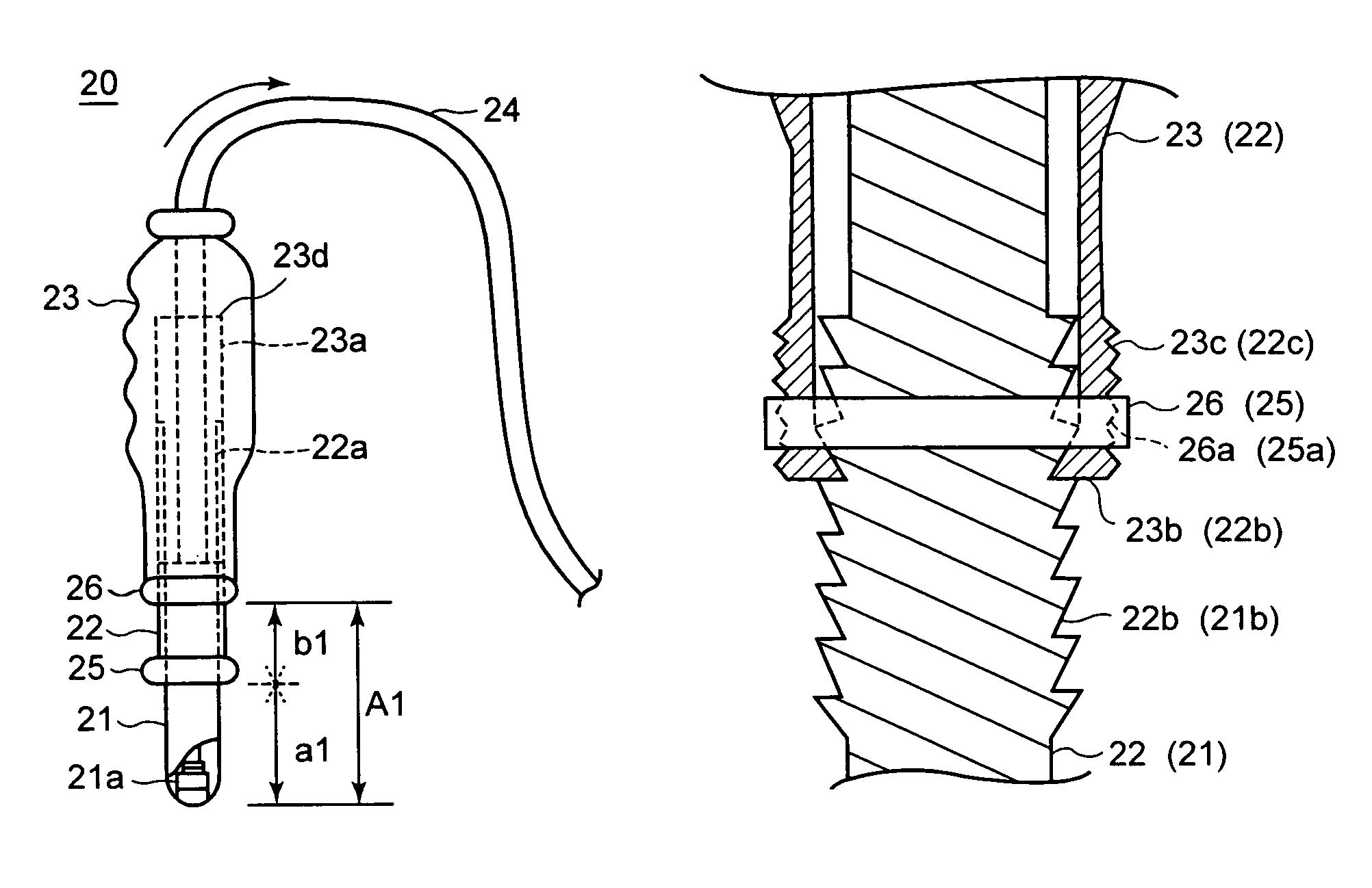
[0051]FIGS. 8A and 8B are illustrations showing an exemplary configuration of an ultrasonic probe according to the third embodiment of the present invention. As shown in FIG. 8A, an endocavity probe 20 is used as an example of the ultrasonic probe according to the third embodiment of the present invention. The endocavity probe 20 includes an insertion end rod (as an example of an insertion end member) 21, a relay rod (as an example of a relay member) 22, a handgrip (as an example of a holding portion) 23, a cable 24, and fixers (or fasteners) 25 and 26.
[0052]The insertion end rod 21 includes an ultrasonic sensor 21a at its head (distal) end and is inserted into an endocavity of the patient P. The abdominal cavity is one example part of an endocavity of the patient P. In one embodiment, the insertion end rod 21 is sufficiently thin so as to reduce an incision size for the insertion of the insertion end rod 21 in the abdominal cavity. This may help reduce patient's discomfort associat...
PUM
 Abstract
Description
Claims
Application Information
 - R&D Engineer
- R&D Manager
- IP Professional
- Industry Leading Data Capabilities
- Powerful AI technology
- Patent DNA Extraction
Browse by: Latest US Patents, China's latest patents, Technical Efficacy Thesaurus, Application Domain, Technology Topic, Popular Technical Reports.
© 2024 PatSnap. All rights reserved.Legal|Privacy policy|Modern Slavery Act Transparency Statement|Sitemap|About US| Contact US: help@patsnap.com