
Screen sounding device, sounding display screen, manufacturing method thereof, and screen sounding system

A screen sound and display screen technology, which is applied in the field of screen sound devices, ultrasonic generators, and screen sound systems, can solve problems such as inability to restore sound and vibration, inability to vibrate and produce sound, and large device volume, so as to save space and reduce costs. Effect

Inactive Publication Date: 2018-12-21
BOE TECH GRP CO LTD
View PDF8 Cites 58 Cited by
  • Summary
  • Abstract
  • Description
  • Claims
  • Application Information

AI Technical Summary

Problems solved by technology

However, the liquid crystal panel has a complex structure and is not a flexible material, so it cannot effectively restore the sound vibration and cannot be used for vibration sound
[0005] In addition, the working principle of this type of screen generating device is to use a traditional exciter attached to the back of the screen to drive the entire display panel to vibrate. Therefore, high power is required and the device is relatively large in size, so it is not suitable for mobile terminals, such as mobile phones, tablets, etc. battery operated and for small size devices

Method used


Image

  • Screen sounding device, sounding display screen, manufacturing method thereof, and screen sounding system
  • Screen sounding device, sounding display screen, manufacturing method thereof, and screen sounding system
  • Screen sounding device, sounding display screen, manufacturing method thereof, and screen sounding system

Examples


Embodiment Construction

[0089] Embodiments of the present invention are described in detail below, examples of which are shown in the drawings, wherein the same or similar reference numerals designate the same or similar elements or elements having the same or similar functions throughout. The embodiments described below by referring to the figures are exemplary and are intended to explain the present invention and should not be construed as limiting the present invention.

[0090] In order to solve the problem that the existing sound emitting device is bulky and cannot be suitable for integration in an ultra-thin and lightweight display device, the present invention proposes a screen sound emitting device. A plurality of ultrasonic generating units distributed on a plane constitute an array, control the ultrasonic generating units at different positions of the array to generate different output components, and through the design and control of the output components, after the ultrasonic components ar...


PUM


Abstract

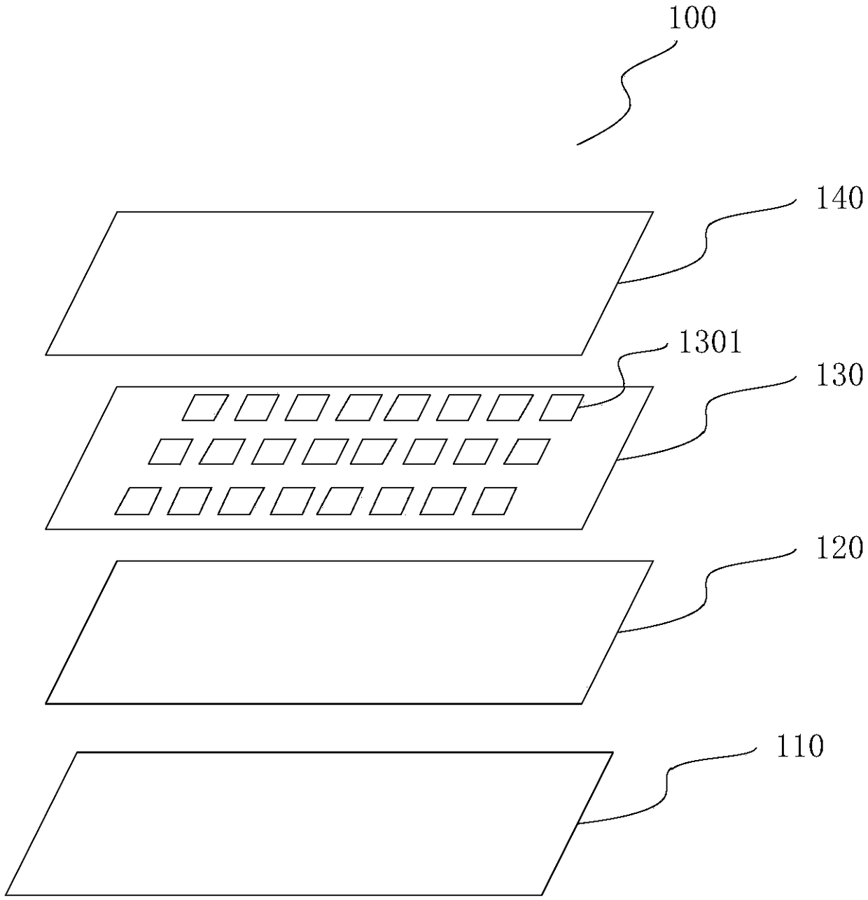
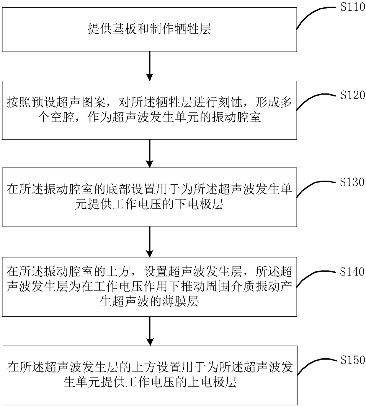
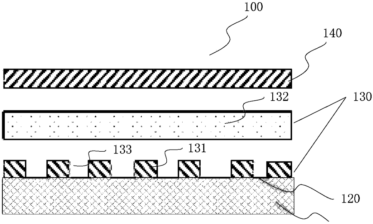
The invention provides an ultrasonic generator, a screen sounding device, a sounding display screen, a manufacturing method thereof and a screen sounding system. The screen sounding device comprises asubstrate, a lower electrode layer, an ultrasonic generating unit array and an upper electrode layer arranged in order from bottom to top, wherein the substrate is used for providing support for thescreen sounding device; the lower electrode layer is disposed on the upper surface of the substrate and includes a lower electrode for supplying the working voltage of each ultrasonic generating unitin the ultrasonic generating unit array. The ultrasonic generating unit array is arranged above the low electrode layer and includes a plurality of ultrasonic generating unit arranged according to a preset ultrasonic pattern; the upper electrode lay is disposed above thet ultrasonic generating cell array and includes an upper electrode for supplying an operating voltage of each ultrasonic generating unit in the ultrasonic generating unit array. Thus, the space occupation of the sound producing device is reduced, the sound producing device is convenient to be integrated with the display panel,and directional sound producing can be realized.

Description

technical field [0001] The invention relates to a technology for generating a sound field and an image display technology, in particular to an ultrasonic generator, a screen sound generating device, a sound emitting display screen, a manufacturing method thereof, and a screen sound generating system. Background technique [0002] The ultra-thin, narrow bezel, and even full-screen designs of display devices leave less and less space for sound-generating devices. However, the traditional sound generating device has a large volume and its installation position is limited, so it is difficult to have a suitable position and space in the new generation of display devices. Therefore, it is necessary to redesign the sound generating device that can adapt to the requirements of the current display device. Moreover, most of the current sound generating devices are based on silicon-based MEMS (Micro-Electro-Mechanical System, Micro-Electro-Mechanical System) structural technology, whi...

Claims


Application Information

Patent Timeline
IPC IPC(8): H04R9/06H04R31/00
CPCH04R9/06H04R31/00H10K59/00H10K59/12H04R17/005H04R19/013H04R1/403H04R2201/401H04R2217/03H04R2499/15H04R2400/01B06B1/0629B06B1/0292
Inventor 韩艳玲王海生丁小梁刘英明王鹏鹏郑智仁张平曹学友
Owner BOE TECH GRP CO LTD
Learn More