Ignition coil

a technology of ignition coil and coil body, which is applied in the direction of transformer/inductance details, inductance, electrical equipment, etc., can solve the problems of high-voltage current generation, crack or leakage of secondary coil, and difficult formation of communication void passages

Active Publication Date: 2009-12-08
DENSO CORP
View PDF7 Cites 8 Cited by
  • Summary
  • Abstract
  • Description
  • Claims
  • Application Information

AI Technical Summary

Problems solved by technology

However, when defect of the filling resin occurs in the ignition coil, an air gap due to the defect may generate a void (bubble).
In a case, where the void moves to a peripheral portion, such as the primary coil or secondary coil, before the filling resin is set, the void may cause a crack or leakage of high-voltage current in the secondary coil.
Thus, it is not easy to form the communicated void passage.
In a case, where the aligning part is engaged with an end of the secondary spool on the low-voltage side thereof, it is difficult to sufficiently release a void.
However, a void generated around the periphery of the center core may not be sufficiently released.

Method used


Image

  • Ignition coil
  • Ignition coil
  • Ignition coil

Examples


Embodiment Construction

[0020]An embodiment of the ignition coil of the present invention will be described below with reference to the drawings.

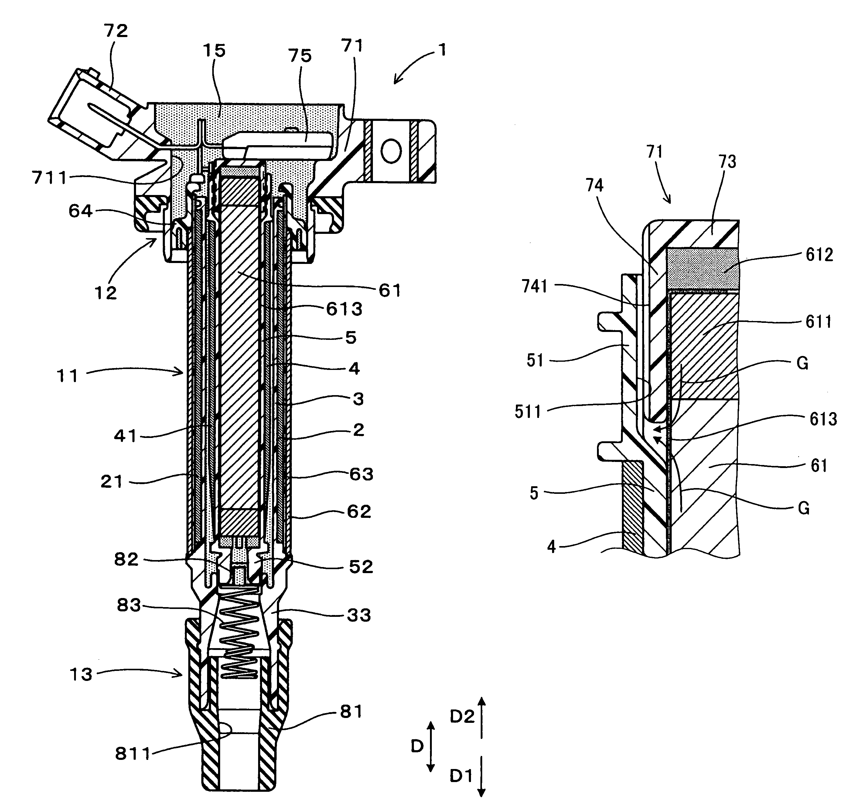
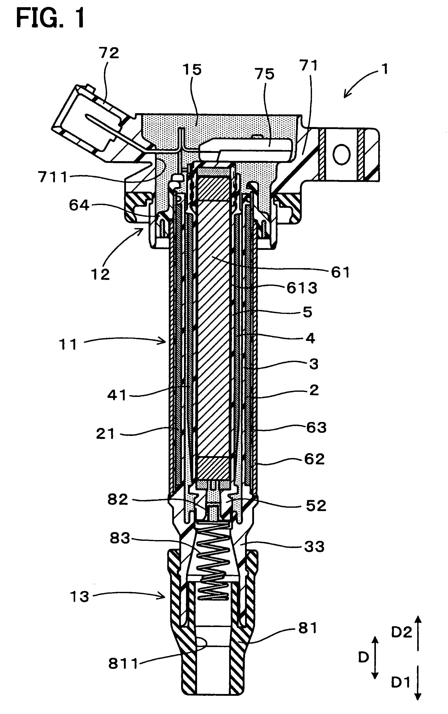
[0021]As shown in FIG. 1, an ignition coil 1 of the embodiment has a coil body 11 and a connector 12. The coil body 11 has a rod-shaped center core 61, a primary coil 2, and a secondary coil 4, and the center core 61 is made of a magnetic material that is disposed on an inner periphery side of the primary coil 2 and the secondary coil 4. The connector 12 is coupled to an end of the coil body 11 on a low-voltage side thereof (an end of the coil body 11 in a direction D2). In the ignition coil 1, the primary coil 2 and the secondary coil 4 are housed in a coil case 63, and clearances in the coil case 63 and the connector 12 are filled with a filling resin 15 for fixing and electrically insulating the components.

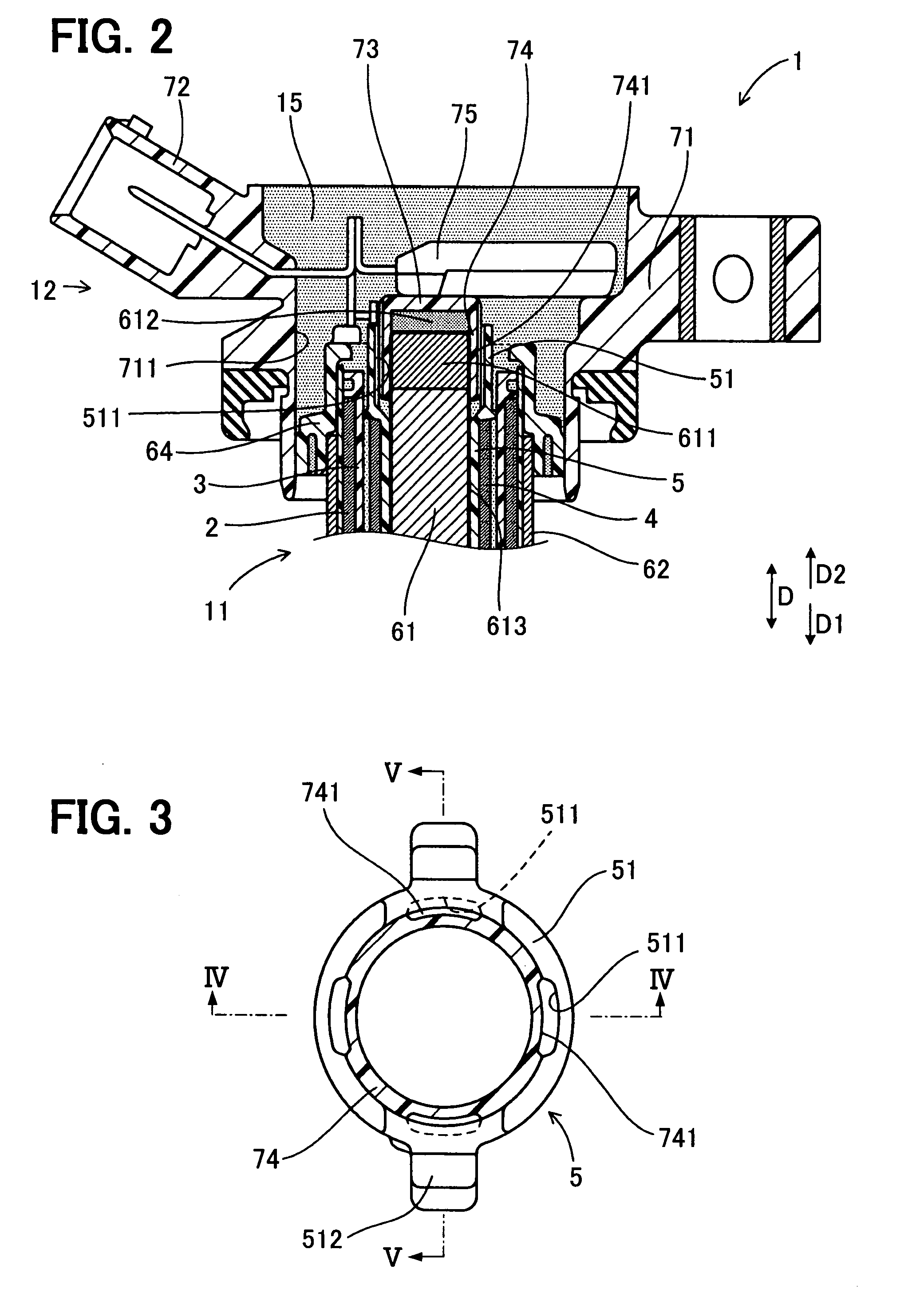
[0022]As shown in FIGS. 2 to 4, the connector 12 is provided with an aligning part 74 for centering the center core 61 (e.g., for centering the center core 6...


PUM

PropertyMeasurementUnit
sizeaaaaaaaaaa
thicknessaaaaaaaaaa
voltageaaaaaaaaaa

Abstract

An ignition coil includes a coil body, a connector, a coil case, a filling resin, and a vent groove. The coil body includes a primary coil, a secondary coil, and a center core. The secondary coil has a secondary spool and a secondary wire wound around the spool. The center core is provided on an inner peripheral side of the secondary spool. The connector is coupled with an end of the coil body. The connector has an aligning part adapted for centering the center core. An end of the secondary spool has a tubular shape adapted for engagement with an outer periphery of the aligning part. The vent groove is provided to facing surfaces of the aligning part and of the end of the second spool. The vent groove is adapted for releasing gas around the center core to an exterior of the secondary spool.

Description

CROSS REFERENCE TO RELATED APPLICATION[0001]This application is based on and incorporates herein by reference Japanese Patent Application No. 2006-205270 filed on Jul. 27, 2006.BACKGROUND OF THE INVENTION[0002]1. Field of the Invention[0003]The present invention relates to an ignition coil used for generating a spark between a pair of electrodes in a spark plug in an internal combustion engine.[0004]2. Description of Related Art[0005]In an ignition coil used for an internal combustion engine, for example, a primary coil formed by winding a primary wire around a primary spool is disposed concentrically with a secondary coil formed by winding a secondary wire around a secondary spool so as to oppose with each other in a radial direction. A center core made of a magnetic material is disposed on an inner peripheral side of the primary and secondary coils, a peripheral core made of a magnetic material is disposed on the outside of the primary and secondary coils, and a magnetic circuit f...

Claims


Application Information

Patent Timeline
Patent Type & Authority Patents(United States)
IPC IPC(8): H01F27/02
CPCH01F38/12H01F27/002H01F2038/122
Inventor FUJIYAMA, NORIHITO
Owner DENSO CORP
Why Eureka
Try Eureka