Control apparatus for internal combustion engine

a control apparatus and internal combustion engine technology, applied in the direction of electric control, muscle operated starters, instruments, etc., can solve the problems of stalling, reverse rotation may be erroneously detected, and the startup of an internal combustion engine may be disabled, so as to prevent the start from being disabled

Inactive Publication Date: 2009-03-05
KEIHIN CORP
View PDF7 Cites 22 Cited by
  • Summary
  • Abstract
  • Description
  • Claims
  • Application Information

AI Technical Summary

Benefits of technology

[0019]The invention has been conceived in view of the above-described circumstances, and it is an object of thereof to provide a control apparatus for an internal combustion engine in which it is possible to improve the reverse rotation detection accuracy of an internal combustion engine, and prevent rebounding of kick pedal more reliably.
[0020]Furthermore, it is another object of the invention to provide a control apparatus for an internal combustion engine in which it is possible to prevent disabled startup, and any damage of parts constituting a startup drive system or an internal combustion engine body, after reverse rotation of the internal combustion engine was detected.

Problems solved by technology

In the above conventional techniques, when any noises are generated in output voltage signals of the magnet-type AC generator that is used for detection of reverse rotation (including the exciter coil), the reverse rotation may be erroneously detected only by detecting the predetermined phases of these signals once.
Furthermore, startup of an internal combustion engine may be disabled, or there is concern that an engine stall is caused if the engine is under operation.
Furthermore, when an abnormality, such as a case where the magnet-type AC generator or the exciter coil is short-circuited from other power sources (e.g., a multi-phase generator or a battery), the reverse rotation cannot be detected, and rebounding of kick pedal cannot be prevented.
Furthermore, when the pulse number of the AC generator, crank signal input, and elapsed time are adopted as release conditions of the reverse rotation detection result, since engine forward rotation is not detected, there is concern that the reverse rotation detection result (ignition output permission) is released at the time of reverse rotation.
In that case, parts (e.g., starter idle gears, and an engine body) constituting a startup drive system may be damaged.

Method used


Image

  • Control apparatus for internal combustion engine
  • Control apparatus for internal combustion engine
  • Control apparatus for internal combustion engine

Examples


first embodiment

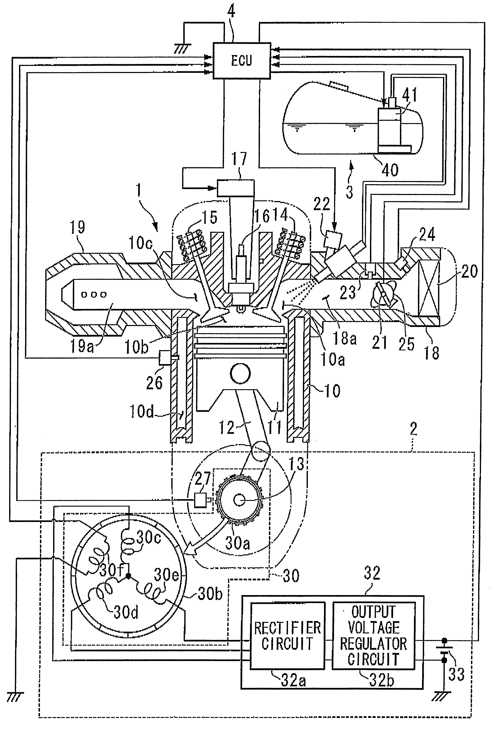
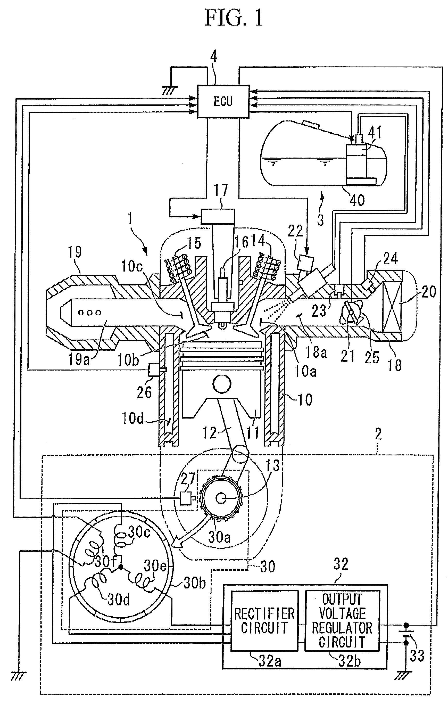
[0135]Next, the reverse rotation prevention processing of an ECU 4 (in particular, a CPU 55) during the operation of an engine 1 in an engine control system that is provided with the ECU 4 (a control apparatus for an internal combustion engine) of a first embodiment that is constructed in the manner described above will be described.

[0136]In addition, as the reverse rotation prevention processing, the CPU 55 executes coil voltage polarity determination processing for determining the polarity of alternating voltage signals output from the reverse rotation detecting coil 30f, and reverse rotation detection processing for detecting the reverse rotation of the engine 1 on the basis of a polarity determination result by this coil voltage polarity determination processing in parallel. Hereinafter, the coil voltage polarity determination processing will first be described.

[0137]Coil Voltage Polarity Determination Processing

[0138]FIG. 4 is a timing chart showing the correspondence relations...

second embodiment

[0189]Next, the invention will be described.

[0190]In the second embodiment, release processing (hereinafter referred to as “reverse rotation release processing”) of a reverse rotation detection result of the ECU 4 (in particular, of the CPU 55) during the operation of the engine 1 in the engine control system that is provided with the ECU 4 (i.e., the control apparatus for an internal combustion engine) that is constructed in the manner described above will be described.

[0191]Specifically, in the reverse rotation release processing in the second embodiment, a case where the crank angle reference position has been detected after the detection of reverse rotation is determined to be returned to a forward rotation state, and the reverse rotation detection result (ignition output prohibition) is released.

[0192]In addition, in the following second embodiment, the same components as those of the above first embodiment are denoted by the same reference numerals, and the description thereof...

third embodiment

[0268]Next, the invention will be described.

[0269]In the reverse rotation release processing in the third embodiment, a case where 720° engine stroke determination has been completed after the detection of reverse rotation is determined to be returned to a forward rotation state, and the reverse rotation detection result (ignition output prohibition) is released.

[0270]In addition, in the following third embodiment, the same components as those of the above first and second embodiments are denoted by the same reference numerals, and the description thereof is omitted.

[0271]It is to be noted in the following description that the structure of the rotor 30a differs from that of the above second embodiment.

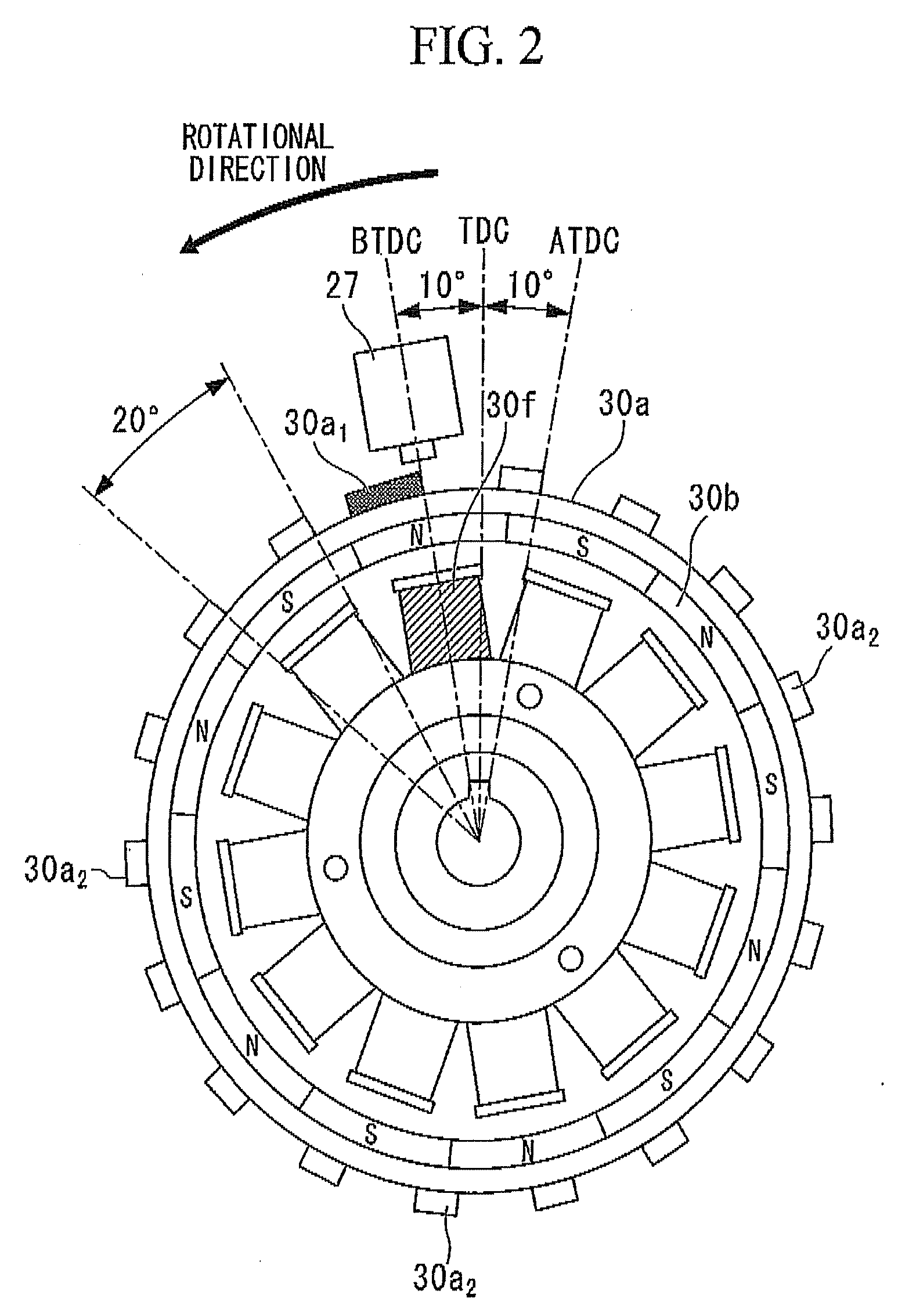
[0272]That is, as shown in FIG. 14, a rotor 30a′ used in the third embodiment has a structure in which auxiliary projections 30a2 are provided instead of the crank angle reference projections 30a1 and the auxiliary projections 30a2 that were provided in 70° and 90° positions backward f...


PUM


Abstract

A control apparatus for an internal combustion engine, includes: a crankshaft; a crank angle detection unit; a generator; and a control unit to which alternating voltage signals are input, that ascertains ignition timings based on crank signals, performs ignition control so as to spark the internal combustion engine at the ignition timings, performs polarity determination processing in which the control unit determines a polarity of the alternating voltage signal each predetermined cycle and determines a current polarity determination result, and performs reverse rotation detection processing in which the control unit obtains the current polarity determination result each time the crank signal is detected so that the control unit ascertains a polarity cycle of the alternating voltage signals and in which the control unit determines that the crankshaft is in reverse rotation and stops the ignition control.

Description

BACKGROUND OF THE INVENTION[0001]This application is based on and claims priority from Japanese Patent Application No. 2007-223193, filed on Aug. 29, 2007, and Japanese Patent Application No. 2007-223064, filed on Aug. 29, 2007, the contents of which are incorporated herein by reference,[0002]1. Field of the Invention[0003]The present invention relates to a control apparatus for an internal combustion engine, and particularly, to a control apparatus for an internal combustion engine having a reverse rotation detecting function of the internal combustion engine.[0004]2. Description of Related Art[0005]When ignition is made before a compression top dead center in a case where the rotational speed of a crankshaft is insufficient at the startup (cranking) of an internal combustion engine by manual operation, a phenomenon, so-called rebounding of kick pedal in which the crankshaft makes reverse rotation and a reverse rotation load is applied to manual starting operation devices (e.g., ki...

Claims


Application Information

Patent Timeline
Patent Type & Authority Applications(United States)
IPC IPC(8): F02D45/00
CPCF02D41/009F02N3/04F02P11/02F02N2250/04F02N11/10
Inventor ISHIKAWA, SHINICHITOKUGAWA, KAZUHITO
Owner KEIHIN CORP
Why Eureka
Try Eureka