Dual coil ignition system

a dual-coil ignition and coil technology, applied in the direction of spark gap circuits, machines/engines, mechanical equipment, etc., can solve problems such as systems that devalue operation, achieve efficient operation of spark plugs, improve peak power output, and prolong the effect of spark duration

Active Publication Date: 2014-12-11
FORD GLOBAL TECH LLC
View PDF9 Cites 20 Cited by
  • Summary
  • Abstract
  • Description
  • Claims
  • Application Information

AI Technical Summary

Benefits of technology

[0002]Engine systems may be configured with boosting devices, such as turbochargers or superchargers, for providing a boosted aircharge and improving peak power outputs. Responsive to the boosted output provided by such engine systems, efficient operation of a spark plug and stable combustion may be achieved by providing high peak secondary currents at high speed and high load conditions, while providing long spark durations at low speeds and loads under lean and / or dilute conditions. However, high peak secondary currents and long spark durations are competing characteristics for ignition coil configuration, resulting in systems that devalue operation under one or more of the above-identified conditions in favor of another condition.
[0004]In this way, each the two coils may be configured for a different one of the competing characteristics (e.g., high peak secondary currents or long spark duration), and steering diodes combine the output of each coil such that additional spark energy is only provided when operating conditions warrant.
[0005]The present disclosure may offer several advantages. For example, by only providing long spark duration when operating conditions call for additional spark energy, overall electrical energy consumption may be decreased in comparison to systems that always provide long spark duration. Further, the configuration decreases component stress, thereby extending component life span, by exposing the current steering diodes to a much lower maximum voltage in comparison to diodes utilized in parallel connected dual coil ignition systems. Furthermore, the lower maximum voltage enables compact coil packaging of a plug top coil positioned on top of a pencil or stick coil, thereby decreasing packaging real estate requirements on the engine in comparison to dual coil systems that are constructed with two side by side plug top coils in one housing or two separate coil packages.

Problems solved by technology

However, high peak secondary currents and long spark durations are competing characteristics for ignition coil configuration, resulting in systems that devalue operation under one or more of the above-identified conditions in favor of another condition.

Method used


Image

  • Dual coil ignition system
  • Dual coil ignition system
  • Dual coil ignition system

Examples


Embodiment Construction

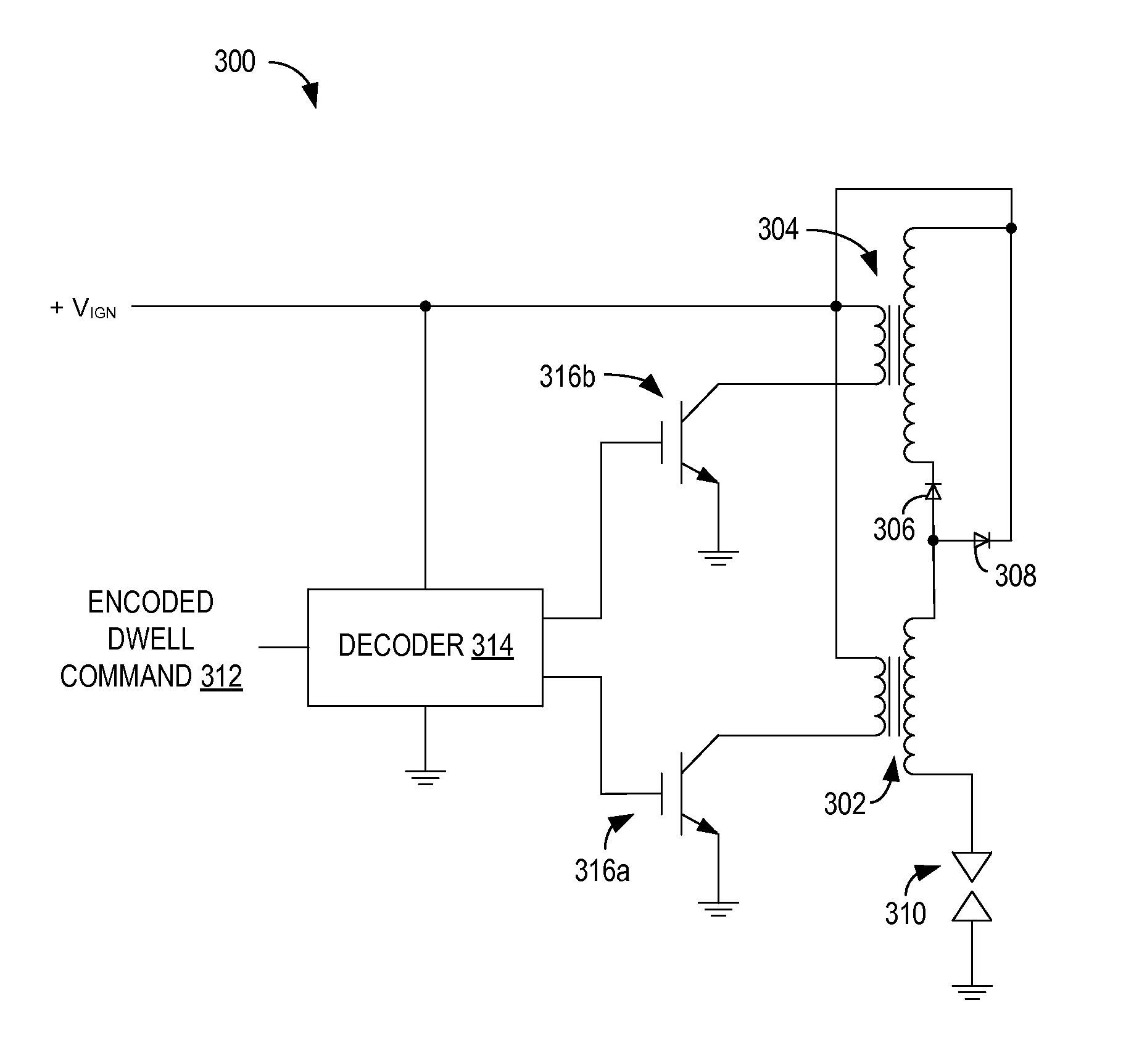
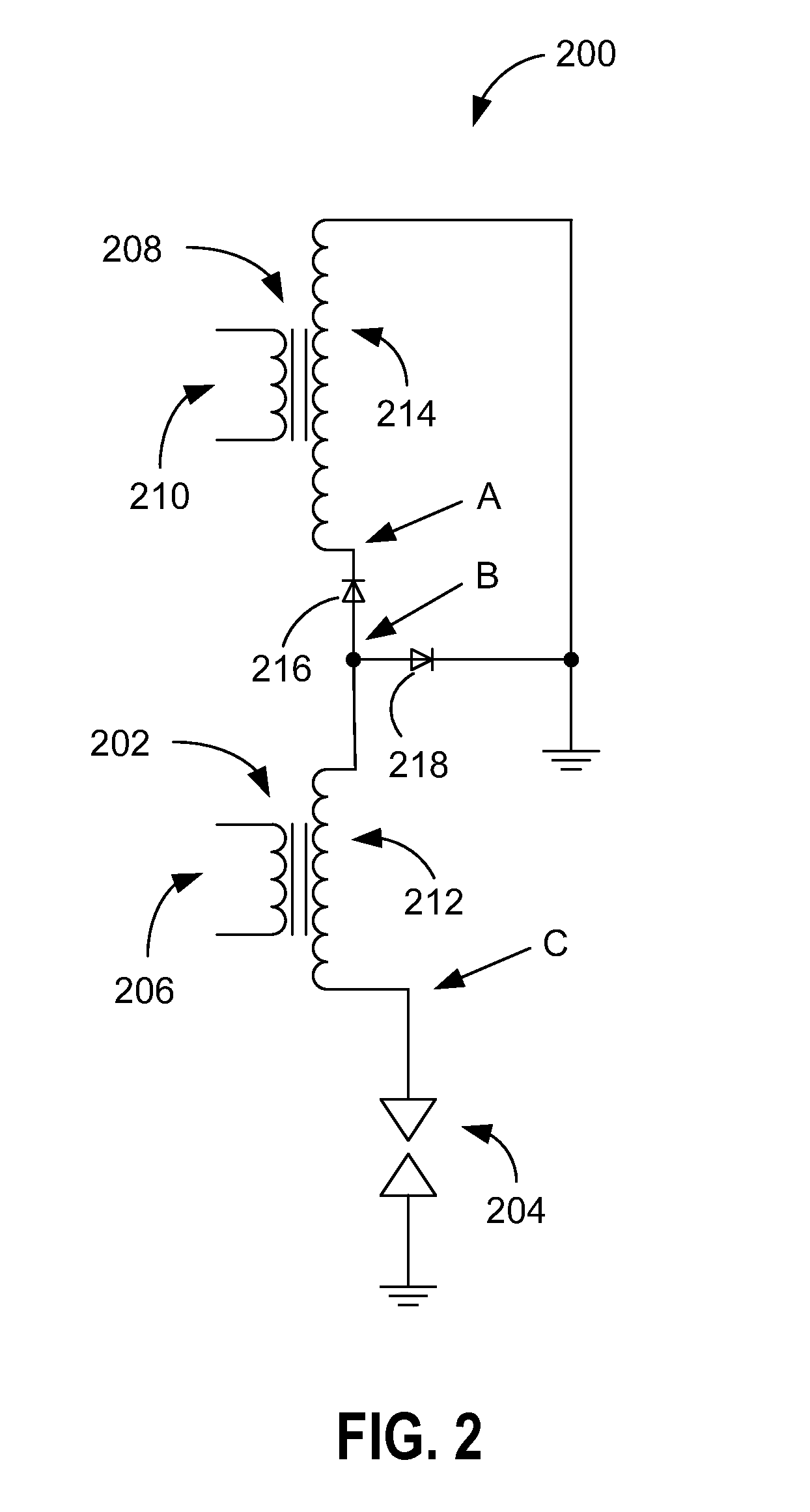
[0014]A dual coil ignition system having secondary windings connected in series via a current steering diode network is disclosed herein. The series-connection of the two ignition coils enables efficient control by allowing independent control of start of dwell times, while ending dwell for each ignition coil simultaneously with a single command. By connecting a relatively low inductance ignition coil to a relatively high inductance ignition coil, the resulting configuration provides high peak secondary currents and long spark duration based on combustion conditions.

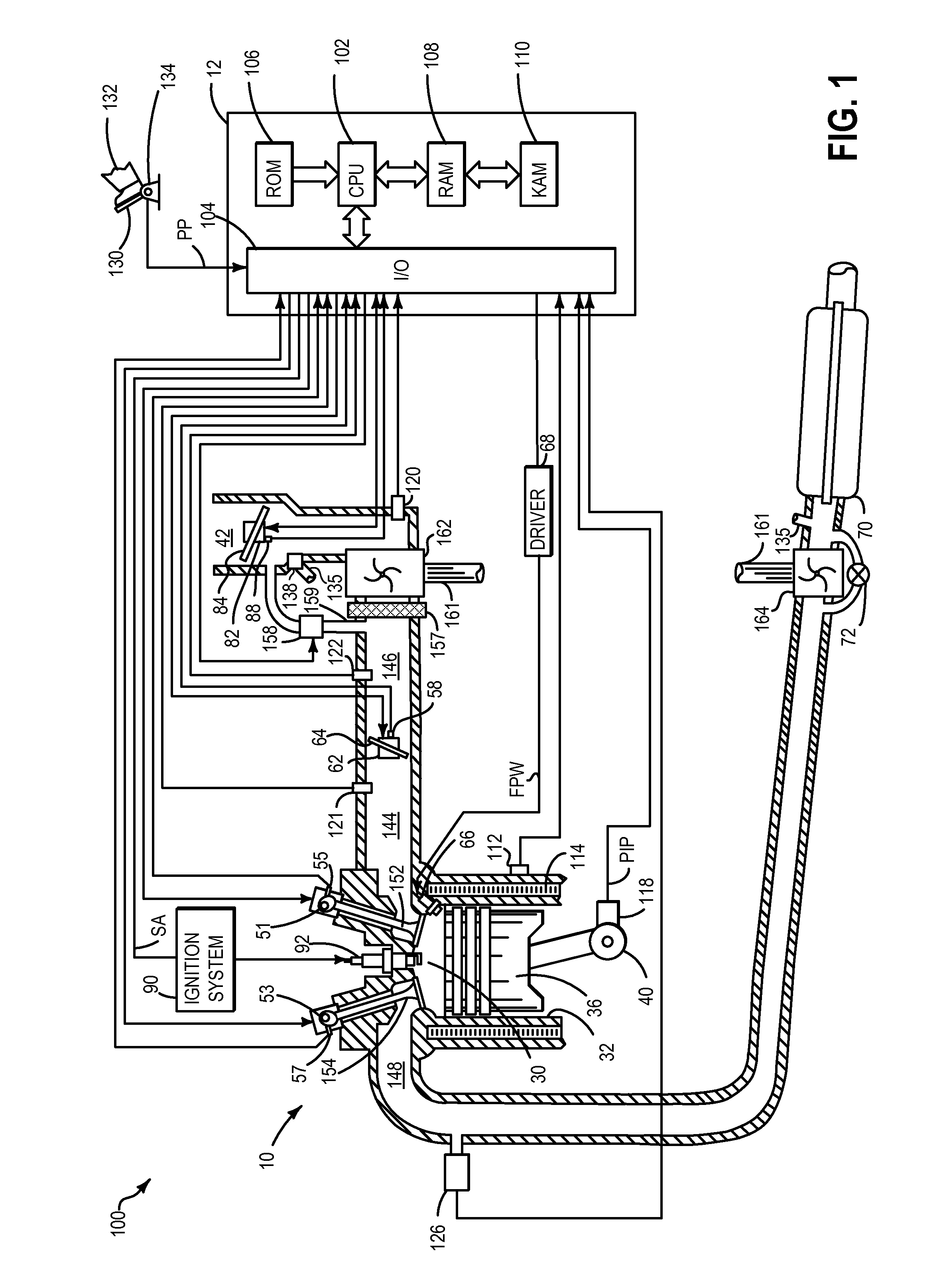
[0015]FIG. 1 depicts an engine system 100 for a vehicle. The vehicle may be an on-road vehicle having drive wheels which contact a road surface. Engine system 100 includes engine 10 which comprises a plurality of cylinders. FIG. 1 describes one such cylinder or combustion chamber in detail. The various components of engine 10 may be controlled by electronic engine controller 12. Engine 10 includes combustion chamber 30 a...


PUM


Abstract

A dual coil ignition system is provided. The dual coil ignition system includes a first inductive ignition coil including a first primary winding and a first secondary winding, and a second inductive ignition coil including a second primary winding and a second secondary winding, the second secondary winding connected in series to the first secondary winding. The dual coil ignition system further includes a diode network including a first diode and a second diode connected between the first secondary winding and the second secondary winding.

Description

FIELD[0001]The present disclosure relates to a dual coil ignition system for controlling spark energy provided to a spark plug of an engine.BACKGROUND AND SUMMARY[0002]Engine systems may be configured with boosting devices, such as turbochargers or superchargers, for providing a boosted aircharge and improving peak power outputs. Responsive to the boosted output provided by such engine systems, efficient operation of a spark plug and stable combustion may be achieved by providing high peak secondary currents at high speed and high load conditions, while providing long spark durations at low speeds and loads under lean and / or dilute conditions. However, high peak secondary currents and long spark durations are competing characteristics for ignition coil configuration, resulting in systems that devalue operation under one or more of the above-identified conditions in favor of another condition.[0003]The inventors have recognized the issues with the above approach and offer a system to...

Claims


Application Information

Patent Timeline
Patent Type & Authority Applications(United States)
IPC IPC(8): F02P9/00H01T15/00
CPCH01T15/00F02P9/002F02P3/04H01F38/12F02P3/0453
Inventor HUBERTS, GARLAN J.QU, QIUPINGCZEKALA, MICHAEL DAMIAN
Owner FORD GLOBAL TECH LLC
Why Eureka
Try Eureka