

Liquid crystal panel and liquid crystal display apparatus
a liquid crystal display and liquid crystal technology, applied in the field of liquid crystal panel and liquid crystal display apparatus, can solve the problems of suppression of display unevenness, reduction of color shift, suppression of screen contrast, etc., and achieve the effects of preventing heat from backlighting, enhancing screen contrast, and reducing color shi
- Summary
- Abstract
- Description
- Claims
- Application Information
AI Technical Summary
Benefits of technology
Problems solved by technology
Method used
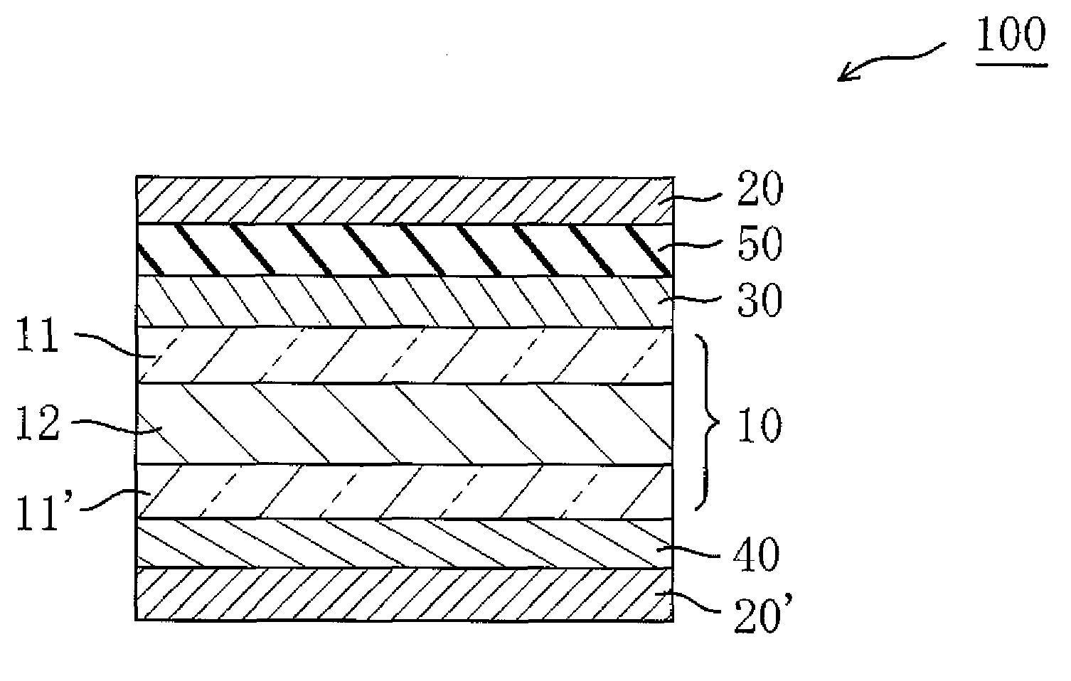
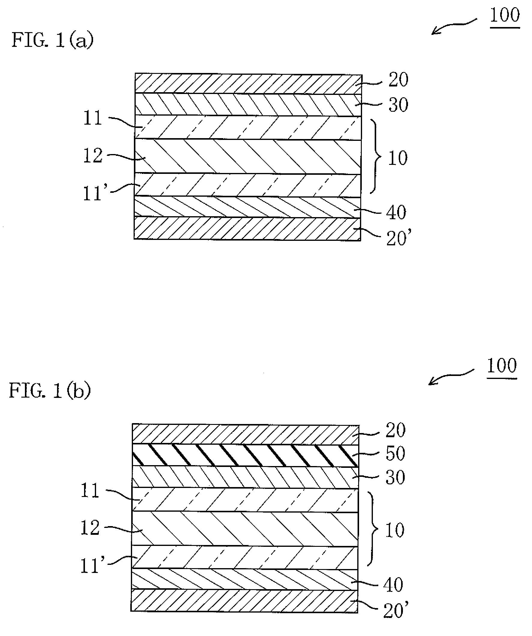
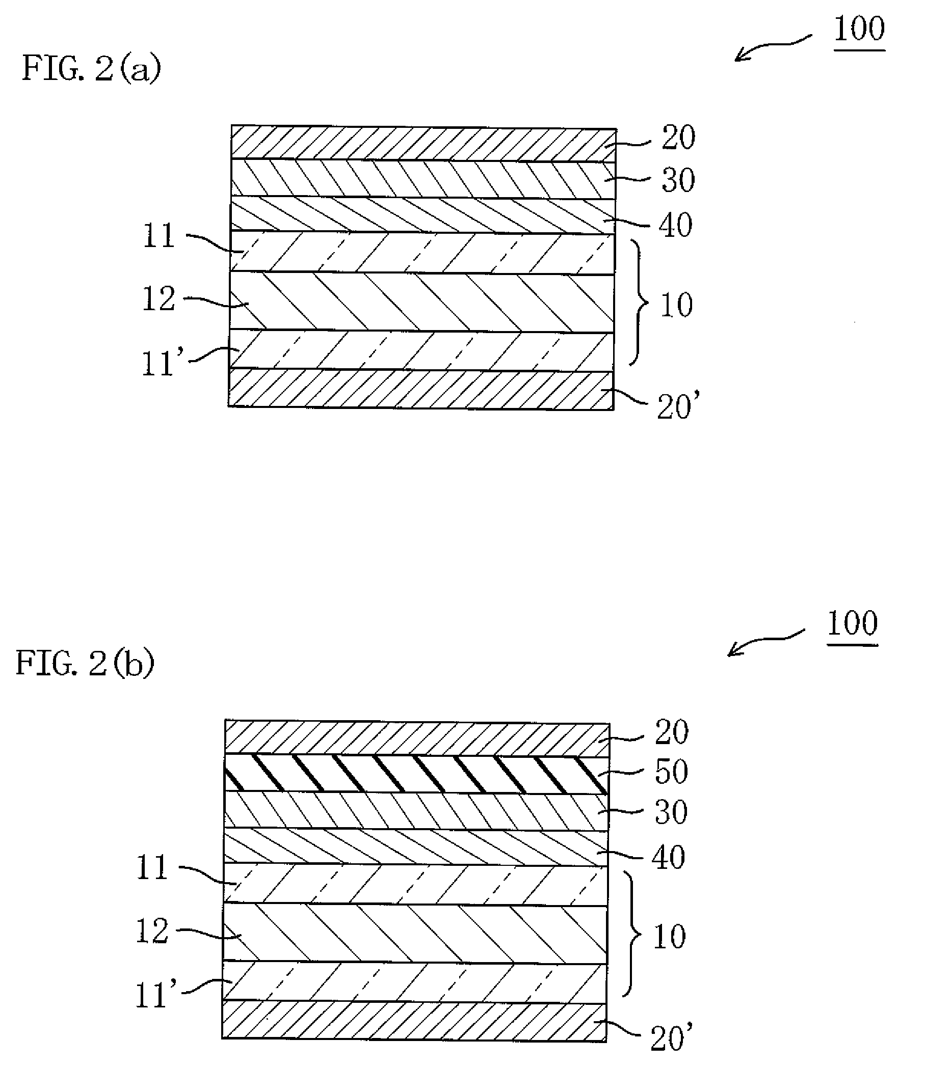
Image

Examples
example 1
(Formation of a First Optical Compensation Layer)
[0153]A film of a cellulose ester with a thickness of 70 μm (manufactured by Kaneka Corporation, trade name: KA, DSac (acetyl substitution degree)=0.04, DSpr (propionyl substitution degree)=2.76) was stretched at a free end to a 1.5 times length of the original length at 145° C. to obtain a first optical compensation layer with a thickness of 68 μm. The photoelastic coefficient of the obtained first compensating layer was 25×10−12 (m2 / N). The in-plane retardation of the obtained first optical compensation layer was Δnd(380)=65 nm, Δnd(550)=90 nm, Δnd(780)=105 nm. The thickness direction retardation Rth(380)=69 nm, Rth(550)=95 nm, Rth(780)=111 nm. The refractive index profile of 550 nm was nx>ny≈nz.
(Production of a Polarizing Plate with a First Optical Compensation Layer)
[0154]The first optical compensation layer obtained in the above was attached to a polarizing plate (manufactured by Nitto Denko Corporation, trade name: SEG1224) havi...
example 2
(Formation of a First Optical Compensation Layer)
[0158]A cellulose ester film (KA (trade name) manufactured by Kaneka Corporation) having a thickness of 70 μm was stretched at a free end to a 1.45 times length of the original length at 145° C., to thereby obtain a first optical compensation layer. The obtained first optical compensation layer had a photoelastic coefficient of 25×10−12 (m2 / N). The obtained first optical compensation layer had in-plane retardations Δnd(380) of 58 nm, Δnd(550) of 80 nm, and Δnd(780) of 93 nm and thickness direction retardations Rth(380) of 65 nm, Rth(550) of 90 nm, and Rth(780) of 105 nm. The obtained first optical compensation layer had a refractive index profile of nx>ny≈nz at 550 nm.
(Formation of a Second Optical Compensation Layer)
[0159]Polyimide synthesized from 2,2-bis(3,4-dicarboxyphenyl)hexafluoropropane dianhydride (6FDA) and 2,2′-bis(trifluoromethyl)-4,4′-diaminobiphenyl (TFMB) was dissolved in methyl isobutyl ketone (MIBK), to thereby prepar...
example 3
(Formation of a First Optical Compensation Layer)
[0161]A cellulose ester film (KA (trade name) manufactured by Kaneka Corporation) having a thickness of 70 μm was stretched at a free end to a 1.55 times length of the original length at 145° C., to thereby obtain a first optical compensation layer. The obtained first optical compensation layer had a photoelastic coefficient of 25×1012 (m2 / N). The obtained first optical compensation layer had in-plane retardations Δnd(380) of 73 nm, Δnd(550) of 100 nm, and Δnd(780) of 117 nm and thickness direction retardations Rth(380) of 76 nm, Rth(550) of 105 nm, and Rth(780) of 123 nm. The obtained first optical compensation layer had a refractive index profile of nx>ny≈nz at 550 nm.
(Formation of a Second Optical Compensation Layer)
[0162]Polyimide synthesized from 2,2-bis(3,4-dicarboxyphenyl)hexafluoropropane dianhydride (6FDA) and 2,2′-bis(trifluoromethyl)-4,4′-diaminobiphenyl (TFMB) was dissolved in methyl isobutyl ketone (MIBK), to thereby prep...
PUM
| Property | Measurement | Unit |
|---|---|---|
| thickness | aaaaa | aaaaa |
| thickness | aaaaa | aaaaa |
| thickness | aaaaa | aaaaa |
Abstract
Description
Claims
Application Information