Direct shaft power measurements for rotating machinery

a technology of rotating machinery and power measurement, which is applied in the direction of instruments, magnetic bodies, sustainable buildings, etc., can solve the problems of calibration and environmental correction requirements, bandwidth limitations, and general low stability of gauges

Active Publication Date: 2009-12-15
GENERAL ELECTRIC CO
View PDF31 Cites 25 Cited by
  • Summary
  • Abstract
  • Description
  • Claims
  • Application Information

AI Technical Summary

Benefits of technology

[0039]One technical effect of the present systems and methods is that the magnetic encoding essentially turns the shaft into a component of the sensing system such that as a mechanical torque is applied to the shaft, a torque-dependent magnetic flux component appears in the direct environment of the encoded region of the shaft.

Problems solved by technology

The gauges generally suffer from low stability, have limitations in the bandwidth and tend to have calibration and environmental correction requirements.
The limited operating temperature range of strain gauges limits their use in a harsh environment.
The tooth-wheel design tends to be costly and impractical for many implementations.
Such a design is not practical for higher speed applications and although stable, lacks high resolution and can cause reliability issues in harsh environment
This system has accuracy issues when applied to large diameter shafts, and there are practical implementation problems.
Making direct use of the magnetostrictive effect for measuring torque in ferromagnetic material requires complex sensor arrangements, difficult calibration procedures and typically results in limited accuracy.
However, the accuracy is limited, the installation process is cumbersome and calibration tends to be difficult.
Furthermore, there are generally tight tolerance requirements for keeping a small gap between the shaft and the sensor that is difficult to achieve with temperature varying environments.
The encoding is circumferentially uniform as the magnetic encoding requires the entire cross-section to be magnetized and therefore becomes difficult and costly for larger diameter shafts.
In addition, there are limitations to this approach with respect to variations of currents due to inhomogeneity of electrical and magnetic properties of the shaft.
Such encoding makes it difficult to achieve a uniform current distribution in circumferential direction, especially with large diameter shafts.
It is not practical for larger shafts as the encoding currents increase with the shaft diameter and large amperage would be required in order to get sufficient flux densities in the large diameter shafts.
Otherwise a sufficiently uniform magnetization in a circumferential direction is not achievable.
Larger spacing requires the section length 80 be larger which causes implementation problems in many applications.
In addition, the individual currents applied to the electrical connections must be controlled to all have the same amplitudes which becomes costly for larger diameter shafts.
Once again, applying this type of sensing it typically inefficient for large diameter shafts.

Method used


Image

  • Direct shaft power measurements for rotating machinery
  • Direct shaft power measurements for rotating machinery
  • Direct shaft power measurements for rotating machinery

Examples


Embodiment Construction

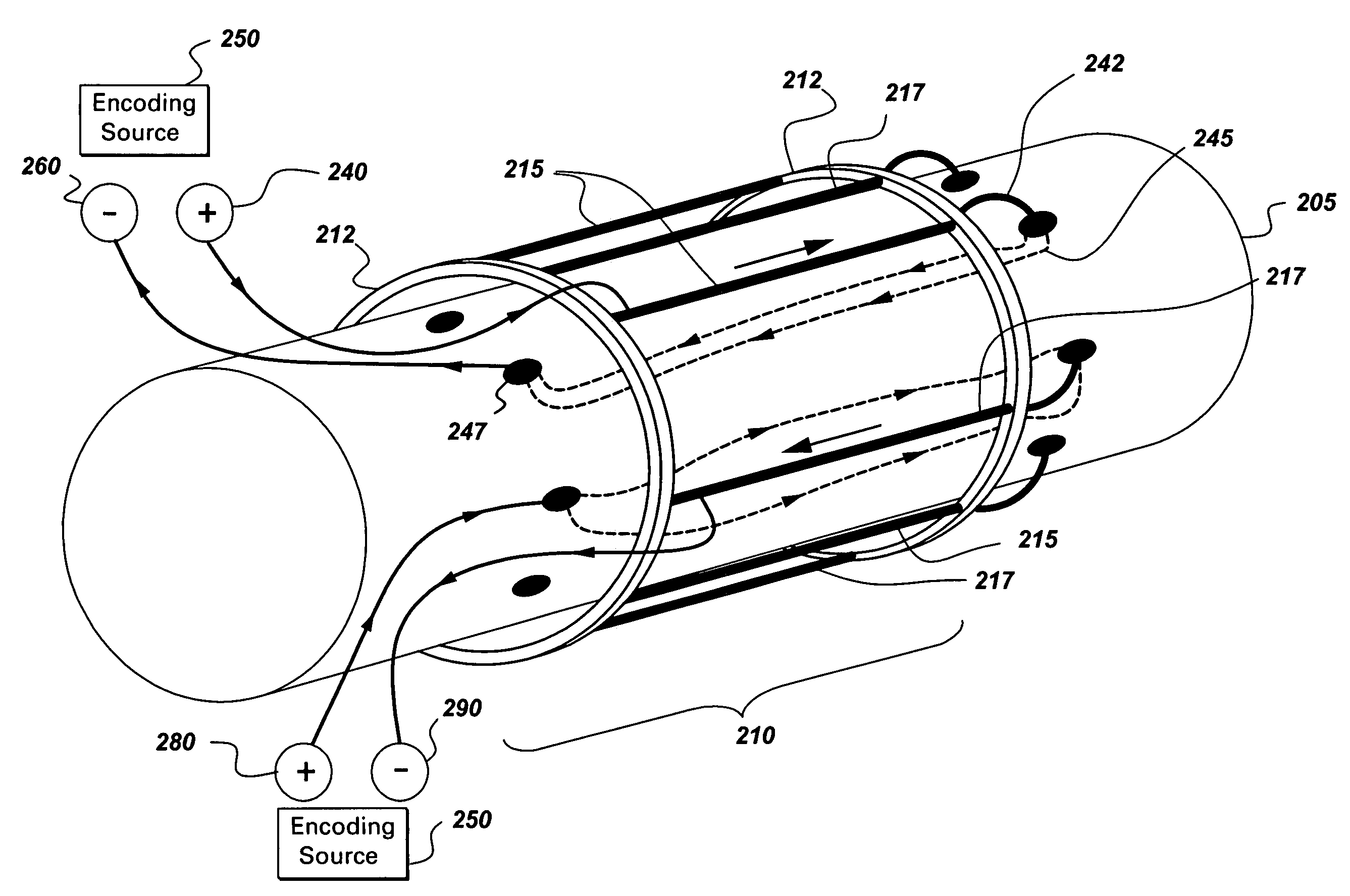
[0053]According to one embodiment, enhanced encoding systems for shafts and measuring properties thereof is achieved by sectional encoding where encoded zones or magnetic channels are generated in axial or circumferential directions of the shaft. For large diameter shafts, it is beneficial to employ this magnetic encoding where relevant flux densities can be achieved with lower encoding currents.

[0054]Referring to FIG. 2, encoding of magnetic polarized regions or channels according to one encoding embodiment is described. As previously noted, the shaft 205 can be a ferromagnetic material or have disposed upon it at least a section of ferromagnetic material affixed to the shaft. The encoding can be accomplished in a number of manners and one manner of operation disposes conducting members 215, 217 such as cables or metallic bars that are arranged about the shaft 205. As depicted, the conducting members 215, 217 extend along the shaft 205 longitudinally, although they may also extend ...


PUM

PropertyMeasurementUnit
diameteraaaaaaaaaa
diameteraaaaaaaaaa
fall timeaaaaaaaaaa

Abstract

Direct shaft power measurements of rotating machinery, including a magnetic encoding system for the shaft, having at least one conducting member having a first end and a second end which is disposed proximate the shaft with a gap between the member and the shaft. There is a pair of electrodes proximate each end of said conducting member, wherein the electrodes are electrically coupled to the shaft. One of the electrodes is electrically coupled to the second end of the conductor member. An encoding source is electrically coupled to the first end of the conducting member and electrically coupled to the other electrode, wherein unipolar current pulses from said encoding source are applied to the electrodes and the conducting member, thereby creating sectional encoded polarized magnetic regions in the shaft.

Description

BACKGROUND OF THE INVENTION[0001]There are numerous applications and industries that are based on rotating shafts to accomplish some form of work or energy conversion. Early examples of rotating shaft functionality include the watermills and windmills thousands of years ago to grind grains. Rotating shafts are still used on current windmills and hydroelectric plants, however they incorporate advanced technology and processing. While small rotating shafts are used in electronic equipment such as computer disk drives, media recorders / players, and household appliances, these shafts are generally of a smaller length and width such that the torque is relatively small. Larger rotating shafts experience larger torque and are deployed in applications including locomotives, airplanes, ships, and energy conversion to name just a few examples. The modern usage of equipment utilizing larger rotating shafts typically incorporates sensing and processing capabilities to achieve safe and efficient ...

Claims


Application Information

Patent Timeline
Patent Type & Authority Patents(United States)
IPC IPC(8): G01L3/10
CPCG01L3/102G01L3/103Y02B10/30H01F13/00H01F13/003
Inventor SIHLER, CHRISTOF MARTINSAMPER, VICTOR DONALDRAUM, KLAUS FRANZ OTTOSCHRAMM, SIMON
Owner GENERAL ELECTRIC CO
Why Eureka
Try Eureka