Optical apparatus and methods for performing eye examinations

an optical instrument and interferometer technology, applied in the field of optical instruments, can solve the problems of inability to measure all required parameters in a single compact apparatus, inconvenient operation, and high accuracy of tests,

an optical instrument and interferometer technology, applied in the field of optical instruments, can solve the problems of inability to measure all required parameters in a single compact apparatus, inconvenient operation, and high accuracy of tests,

US7631970B2Inactive Publication Date: 2009-12-15CARL ZEISS MEDITEC INC

Image

  • Optical apparatus and methods for performing eye examinations
  • Optical apparatus and methods for performing eye examinations
  • Optical apparatus and methods for performing eye examinations

Examples


Embodiment Construction

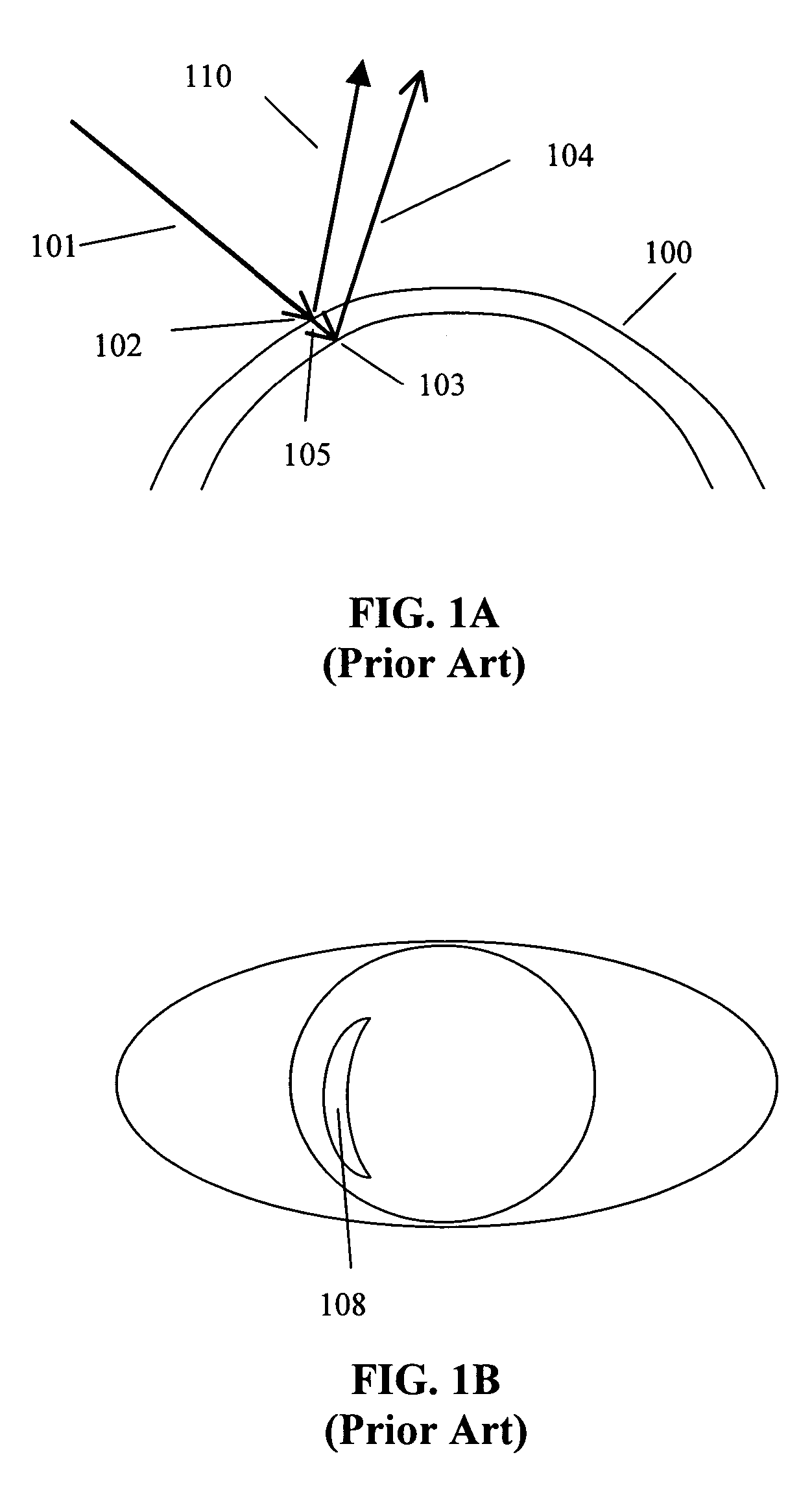
[0020]FIGS. 1A and 1B illustrate a current state-of-the-art slit projection method to measure cornea thickness. As shown in FIG. 1A, a slit of light 101, also referred to herein as a slit beam, is projected on to a cornea 100. Light 110 is reflected from a front surface 102 of cornea 100 and light 104 is reflected from a back surface 103 of cornea 100. Also, because the cornea will scatter light, the segment of cornea stoma 105 will be seen by an observer or CCD camera through an imaging system. A corresponding reflection image 108 from eye 111 of slit beam 101 that is scanned across cornea 100 has a shape of an early moon on the cornea. From an incident angle of slit beam 101 and imaging system parameters, the thickness of cornea 100 can be calculated from the width of a moon-like reflection image 108. In principle, the cornea curvature can also be calculated from reflected light 110 and 104. But limited by the scan speed of the slit beam 101 (in the 1 to 2 seconds range), eye moti...


PUM


Abstract

An eye examination system is presented that obtains several parameters of the eye. A system according to some embodiments of the present invention include a keratometry system, a low coherence reflectometry system, and a low coherence interferometry system co-coupled to the eye. In some embodiments, the low coherence interferometry system can provide interferometric tomography data. A processor can be coupled to receive data from the keratometry system, the low coherence reflectometry system, and the low coherence interferometry system and calculate at least one parameter of the eye from that data.

Description

RELATED APPLICATIONS[0001]The present application claims priority to Provisional Application No. 60 / 543,862, “Optical Apparatus and Methods for Eye Examine, ” by Jay Wei, filed on Feb. 10, 2004, which is herein incorporated by reference in its entirety.BACKGROUND[0002]1. Field of the Invention[0003]The present invention is related to optical apparatus and methods for obtaining parameters in an eye examination and, in particular, to optical interferometric apparatus for performing eye examinations.[0004]2. Discussion of Related Art[0005]Refractive surgery to correct refraction error in the human eye has been widely accepted. Several different types of surgical methods have been explored for this purpose. PRK and LASIK are surgical methods that use laser radiation to ablate cornea tissue in order to change the refractive power of the cornea. Phakic IOL surgery implants intra-ocular lenses in either the anterior or posterior chamber of the eye to compensate for refraction error in the ...

Claims


Application Information

Patent Timeline
15 Dec 2009
Publication
US7631970B2
IPC
A61B3/10; A61B3/00; A45D31/00; A61B3/107; A61B6/00; A61B18/18
CPC
A61B3/102; A45D31/00
Inventors
WEI, JAY