Light emitting diode lamp

a technology of light-emitting diodes and lamps, which is applied in the direction of electrical apparatus contruction details, semiconductor devices of light sources, lighting and heating apparatus, etc., can solve the problems of increasing production costs, poor heat dissipation, and complicated production and long work hours, so as to achieve more economic and efficient heat dissipation

Inactive Publication Date: 2009-12-15
NENG TYI PRECISION INDS
View PDF2 Cites 92 Cited by
  • Summary
  • Abstract
  • Description
  • Claims
  • Application Information

AI Technical Summary

Benefits of technology

[0009]An object of the invention is to provide a light emitting diode lamp which is made more economically and efficiently dissipates the heat from the light emitting diode lamp.
[0021]The invention provides the following advantages. Riveting the heat dissipating fins with the substrate together helps the heat dissipating fins be secured by means of urging the opposite sidewall surfaces of each extending arm against the opposite surfaces of each heat dissipating fin. In addition, there is no need of soldering nickel on the heat dissipating fins and no solder is needed as well. Therefore, the production cost and shortened labor hours can be reduced, while loss of heat conduction can be avoided.

Problems solved by technology

However, the aluminum fins must be coated with chemical nickel before soldering, which increases the production cost, with more complicate production and longer work hours.
Furthermore, since the heat dissipating fins must be soldered, loss in heat conduction occurs due to the difference of heat conduction coefficient between the solder and the heat dissipating fins, resulting in poor heat dissipation.

Method used


Image

  • Light emitting diode lamp
  • Light emitting diode lamp
  • Light emitting diode lamp

Examples


Embodiment Construction

[0030]Wherever possible in the following description, like reference numerals will refer to like elements and parts unless otherwise illustrated.

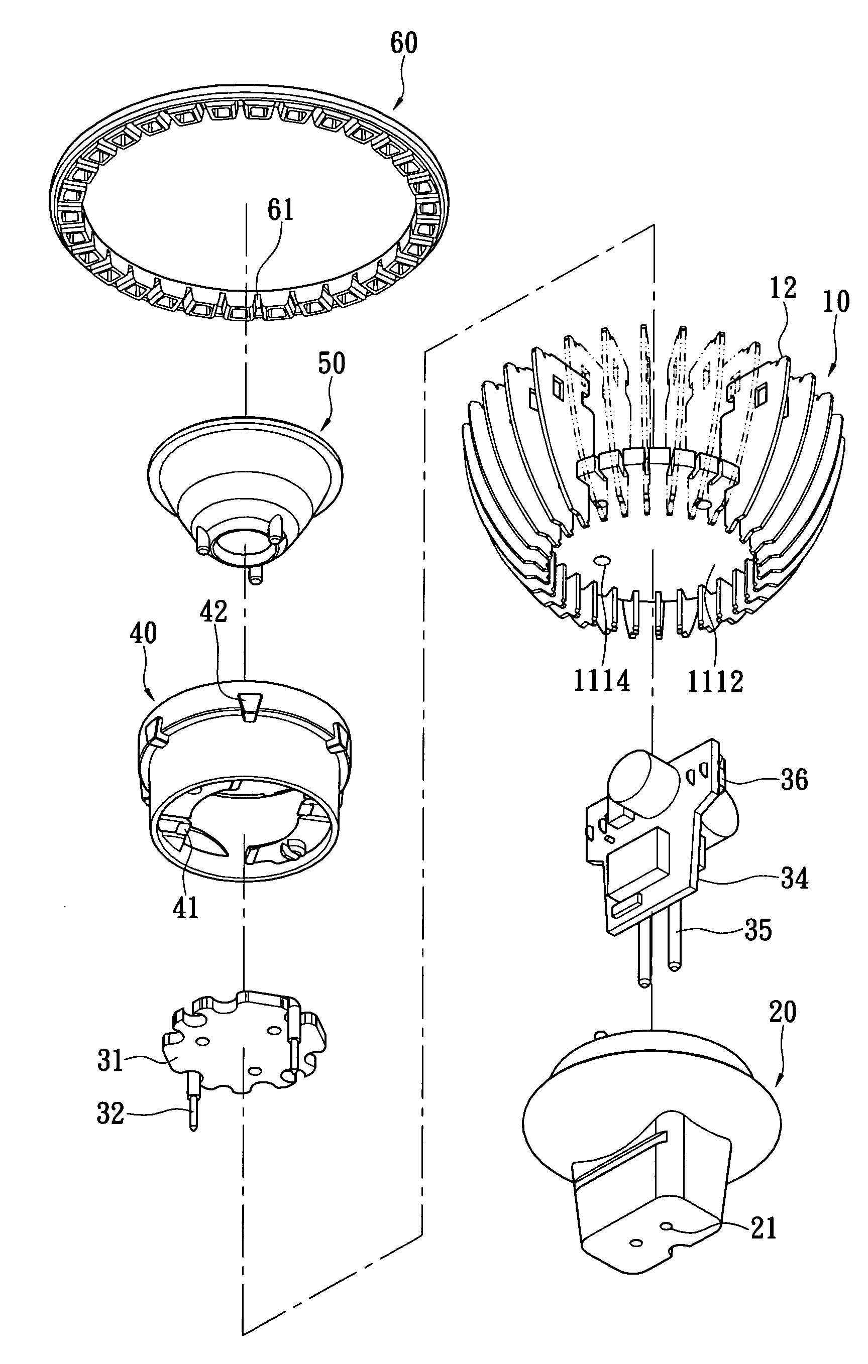
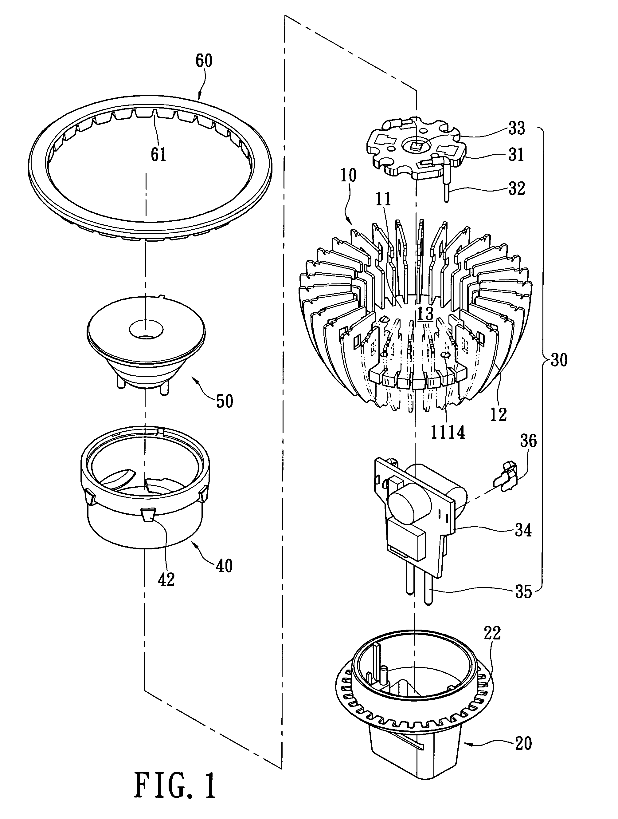
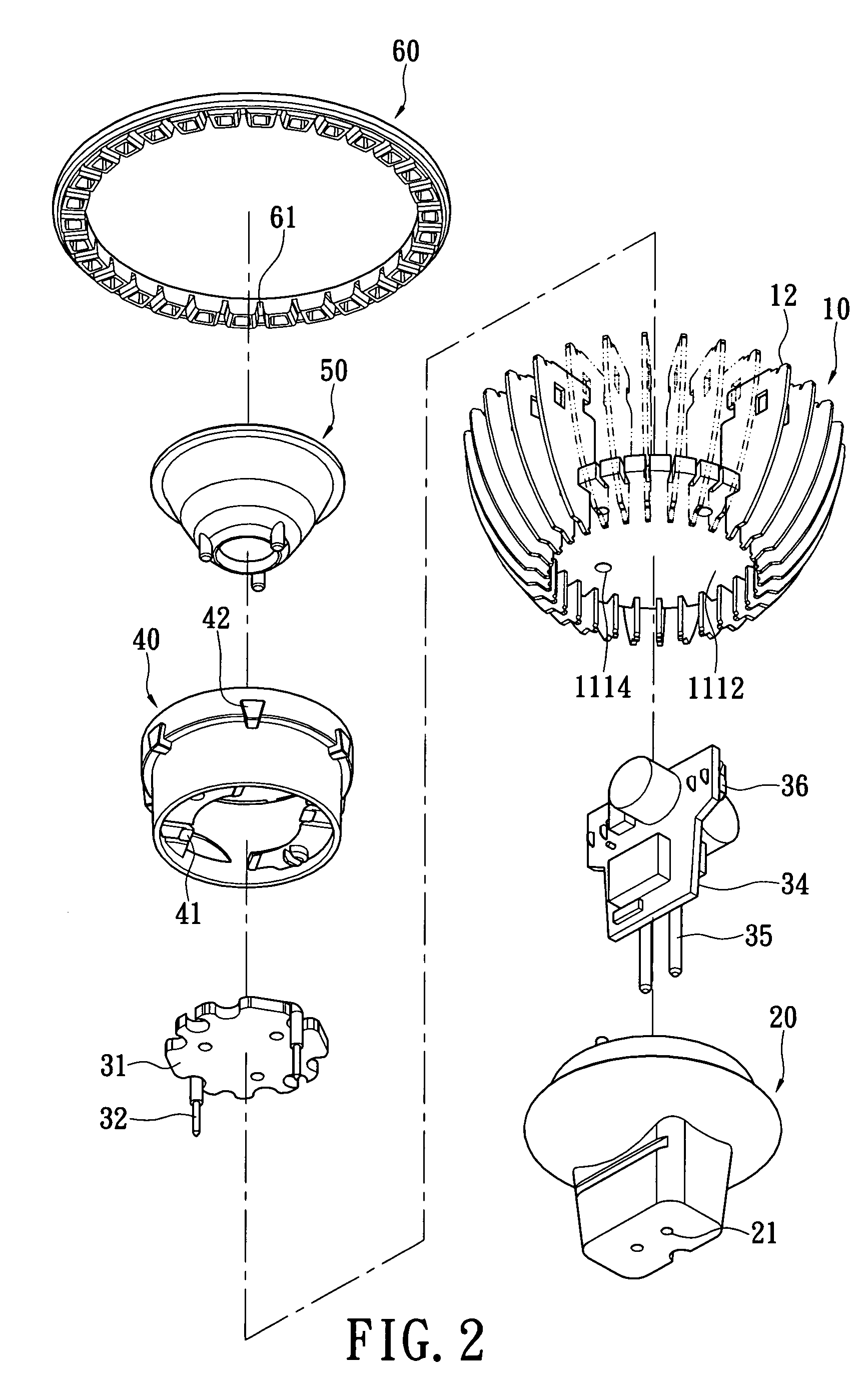
[0031]Referring to FIG. 1 through FIG. 5, a light emitting diode lamp according to one embodiment of the invention includes a heat sink 10, a socket 20, a light emitting module 30, a holder 40, a lens 50 and a protection ring 60.

[0032]Referring to FIG. 6, the heat sink 10 includes a substrate 11 and a plurality of heat dissipating fins 12. The substrate 11 includes a base 111 and a plurality of extending arms 112. The base 111 can be a round plate or a polygonal plate, for example. In the embodiment as shown, the base 111 is a round plate. The base 111 has a top 1111, a bottom 1112 (as shown in FIG. 2), side walls 1113, and trough holes 1114 penetrating through the top 1111 and the bottom 1112.

[0033]The extending arms 112 are positioned at intervals from the side walls 1113 of the base 111. A slot 113 is formed between two neighboring exten...


PUM


Abstract

A light emitting diode lamp includes a heat sink, a socket, a light emitting module, a holder and a lens. The socket and the holder are respectively positioned opposite sides of the heat sink. The light emitting module is combined with the heat sink and has a light emitting diode unit. The lens is mounted on the light emitting diode unit and combined inside the holder. The heat sink includes a substrate and a plurality of heat dissipating fins. The substrate has a plurality of extending arms in a manner that a slot is formed between two neighboring extending arms. A plurality of heat dissipating fins is inserted into the corresponding slots. One of opposite sidewall surfaces of each extending arm is against one of opposite surfaces of each heat dissipating fin. Thereby, there is no need of producing a heat sink by soldering.

Description

BACKGROUND OF THE INVENTION[0001]1. Field of the Invention[0002]The invention generally relates to a light emitting diode lamp, especially to a light emitting diode lamp which meets the MR-16 specification and effectively dissipates the heat from the light emitting diode lamp[0003]2. Description of the Related Art[0004]As the progress of the technology development, the light emitting diode units have been applied to the illumination field. In addition, because of its small volume, low power consumption and long service life, the light emitting diode units have been used in traffic lights, flashlights and lamps.[0005]A conventional light emitting diode lamp is usually disposed with a heat sink to dissipate the heat from the light emitting diode unit. The heat sink is mounted to a plurality of heat dissipating fins by soldering. The heat dissipating fins are made of thermally conductive metal, especially aluminum which is featured as light weight and good heat dissipating performance....

Claims


Application Information

Patent Timeline
Patent Type & Authority Patents(United States)
IPC IPC(8): F21V29/00F21Y101/02H01L33/00H01L33/48H01L33/58H01L33/64
CPCF21V29/004F21K9/1375F21V29/20F21V29/773F21V29/83F21V29/89F21V23/006F21Y2101/02F21K9/23F21Y2115/10F21V29/74
Inventor WEI, WEN-CHEN
Owner NENG TYI PRECISION INDS
Why Eureka
Try Eureka