Bulk resin infusion system apparatus and method

a resin and infusion system technology, applied in the field of resin infusion devices, can solve the problems of undesirable material strength properties and/or surface imperfections, insufficient success of conventional solutions, and voids or dry areas in internal and/or external spaces, etc., to achieve the effect of facilitating infusion of resin into a layup

Active Publication Date: 2009-12-15
THE BOEING CO
View PDF11 Cites 22 Cited by
  • Summary
  • Abstract
  • Description
  • Claims
  • Application Information

AI Technical Summary

Benefits of technology

[0005]The foregoing needs are met, to a great extent, by the present invention, wherein in one respect a system, apparatus and method is provided that in some embodiments facilitates infusing a resin into a layup.
[0009]Yet another embodiment of the present invention pertains to an apparatus for infusing a liquidus resin into a fibrous layer to fabricate an item. The apparatus includes a means for positioning a quantity of resin on a mandrel adjacent to the fibrous layer. The quantity of resin is sufficient to infuse the fibrous layer. The apparatus further includes a means for generating an amount of compressive force on the resin and a means for reducing the viscosity of the resin. The reduced viscosity resin is infused into the fibrous layer in response to the compressive force exceeding a resistance of the resin.
[0010]Yet another embodiment of the present invention relates to a method of infusing a liquidus resin into a fibrous layer to fabricate an item. In this method, a quantity of resin is positioned on a mandrel adjacent to the fibrous layer. The quantity of resin is sufficient to infuse the fibrous layer. In addition, an amount of compressive force is generated on the resin and the viscosity of the resin is reduced. The reduced viscosity resin is infused into the fibrous layer in response to the compressive force exceeding a resistance of the resin.

Problems solved by technology

However, if the plies are insufficiently saturated with epoxy, internal and / or external voids or dry areas may occur.
Such anomalies may result in undesirable material strength properties and / or surface imperfections.
While conventional methods and devices have been employed to overcome these issues, these conventional solutions have not been fully successful.

Method used


Image

  • Bulk resin infusion system apparatus and method
  • Bulk resin infusion system apparatus and method
  • Bulk resin infusion system apparatus and method

Examples


Embodiment Construction

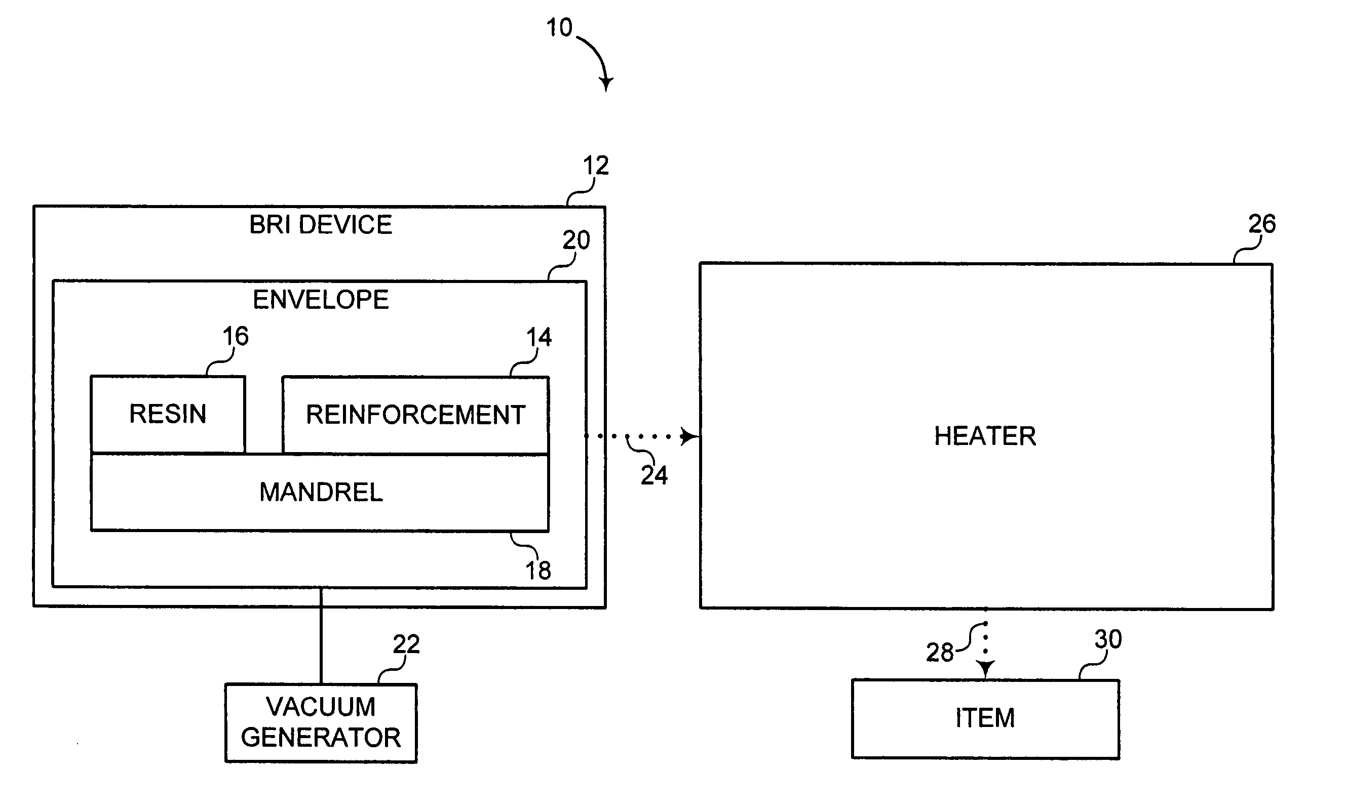
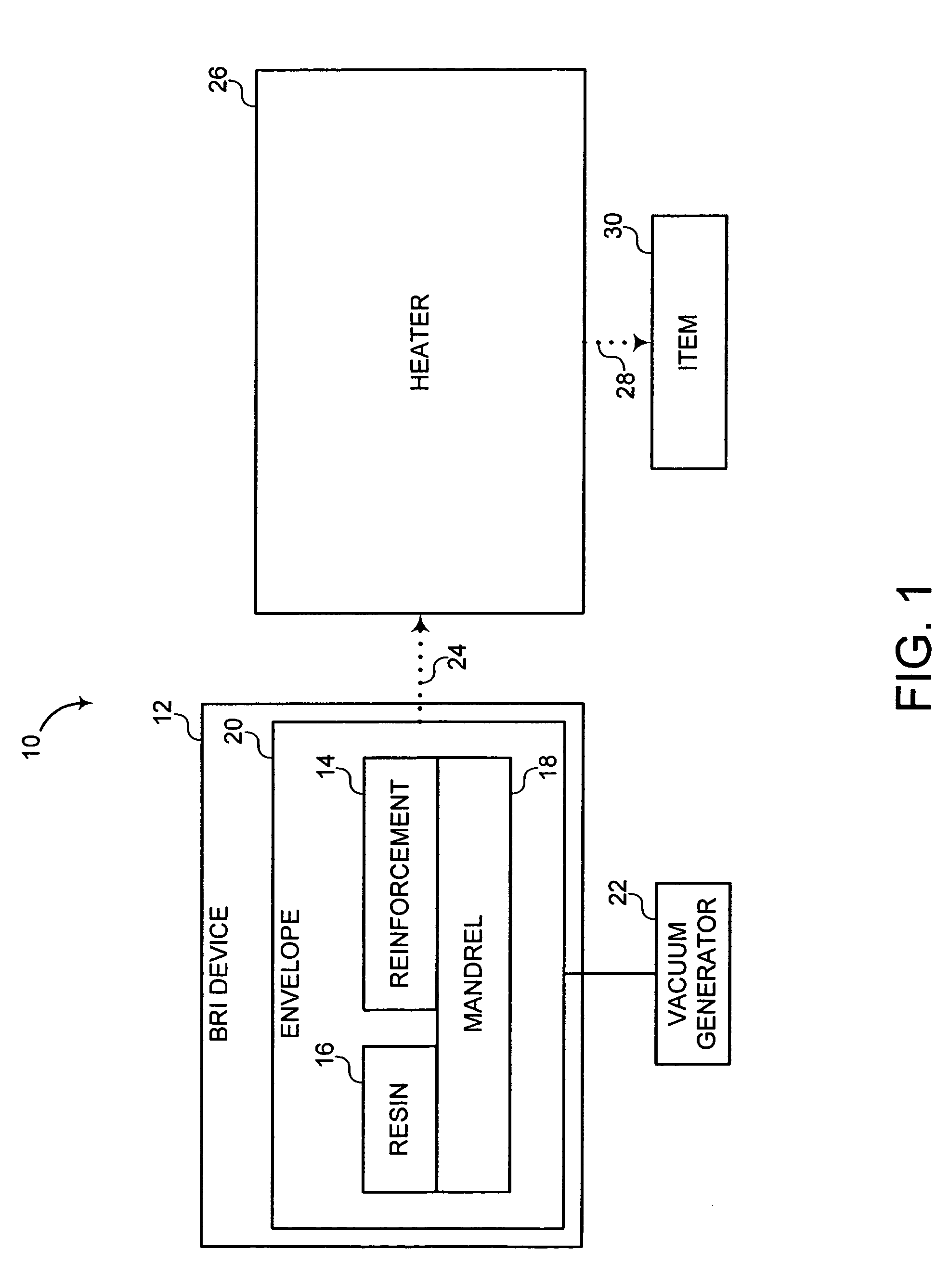
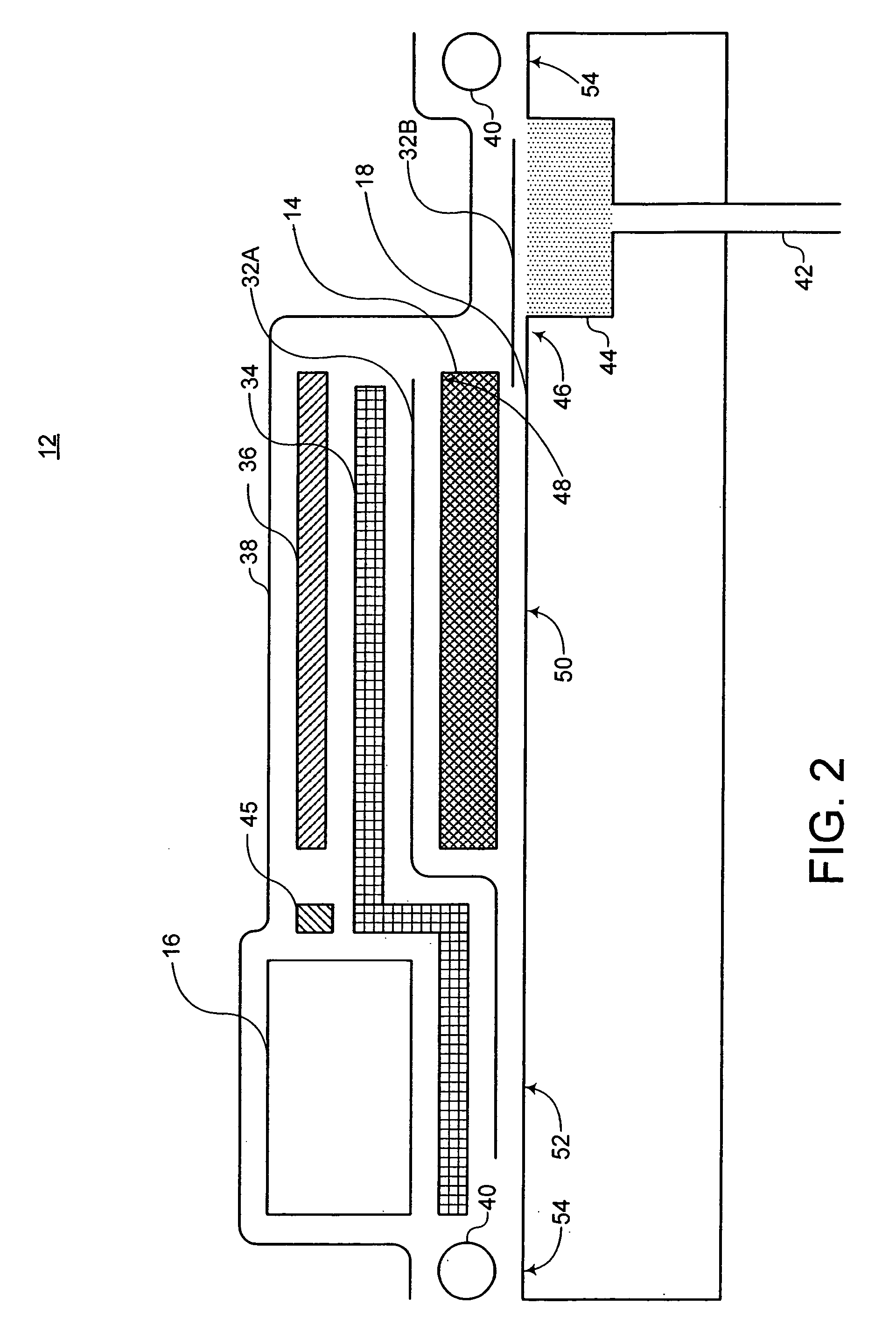
[0022]The present invention provides a vacuum assisted bulk resin infusion (BRI) system, device, and method. In some embodiments, the BRI system includes a form or mandrel to retain a layup. The layup includes at least one ply of preform, parting film, and infusion media. The BRI system includes a membrane that is sealed from the atmosphere or substantially gas impermeable membrane that envelopes the layup. In response to a pressure differential across the membrane, compressive force is exerted upon the layup. This process is typically referred to as “vacuum bagging.” However, increasing ambient pressure outside the envelope may also be utilized. The term, “bulk resin infusion” as used herein, refers to resin being used to infuse the preform at a relatively higher flow rate than convention systems. In an embodiment, this higher flow rate may be achieved by disposing the resin adjacent to the preform and within the envelope. This method reduces or eliminates any tubing systems utiliz...


PUM

PropertyMeasurementUnit
volume fractionaaaaaaaaaa
compressive forceaaaaaaaaaa
viscosityaaaaaaaaaa

Abstract

A composite item is fabricated in system that includes a layer of preform, supply of resin, mandrel, and bagging film. The layer of preform corresponds to the composite item. The supply of resin is sufficient to infuse the preform. The mandrel includes a preform receiving zone to receive the layer of preform and a resin receiving zone to receive the supply of resin. The resin receiving zone is adjacent to the preform receiving zone. The bagging film is operable to generate an envelope surrounding the preform receiving zone and the resin receiving zone.

Description

FIELD OF THE INVENTION[0001]The present invention generally relates to a resin infusion device. More particularly, the present invention pertains to a vacuum assisted resin infusion device.BACKGROUND OF THE INVENTION[0002]Laminated materials such as, for example, composites are widely utilized to increase structural rigidity in a wide variety of products. For example, composites are generally utilized by the airplane construction industry to build airframes, structural members of airframes, wings, wing spars, and the like. In some of the most advanced aircraft, where high strength and rigidity and low weight are extremely important, composites may account for a significant portion of the airframe as well as the external surface or skin. Typically, these composites are constructed from a plurality of layers placed over a form. These layers are often referred to as partial or full plies. Each ply may be in the form of unidirectional fiber material, woven fibers in a fabric, braided, o...

Claims


Application Information

Patent Timeline
Patent Type & Authority Patents(United States)
IPC IPC(8): H05B6/00B29C45/14
CPCB29C70/44B29C33/00
Inventor GLAIN, MICHAEL L.HANKS, DENNIS J.MODIN, ANDREW E.WOODS, JACK A.AQUINO, TIMOTHY D.
Owner THE BOEING CO
Why Eureka
Try Eureka