Magnetic write head with helical coil structure using multiple materials

a write head and helical coil technology, applied in the direction of recording information storage, maintaining the head carrier alignment, instruments, etc., can solve the problems of increased manufacturing complexity and cost, and the difficulty of helical coil construction, so as to achieve the effect of minimal manufacturing steps, minimal manufacturing complexity and efficient manufacturing

Active Publication Date: 2009-12-15
WESTERN DIGITAL TECH INC
View PDF15 Cites 11 Cited by
  • Summary
  • Abstract
  • Description
  • Claims
  • Application Information

AI Technical Summary

Benefits of technology

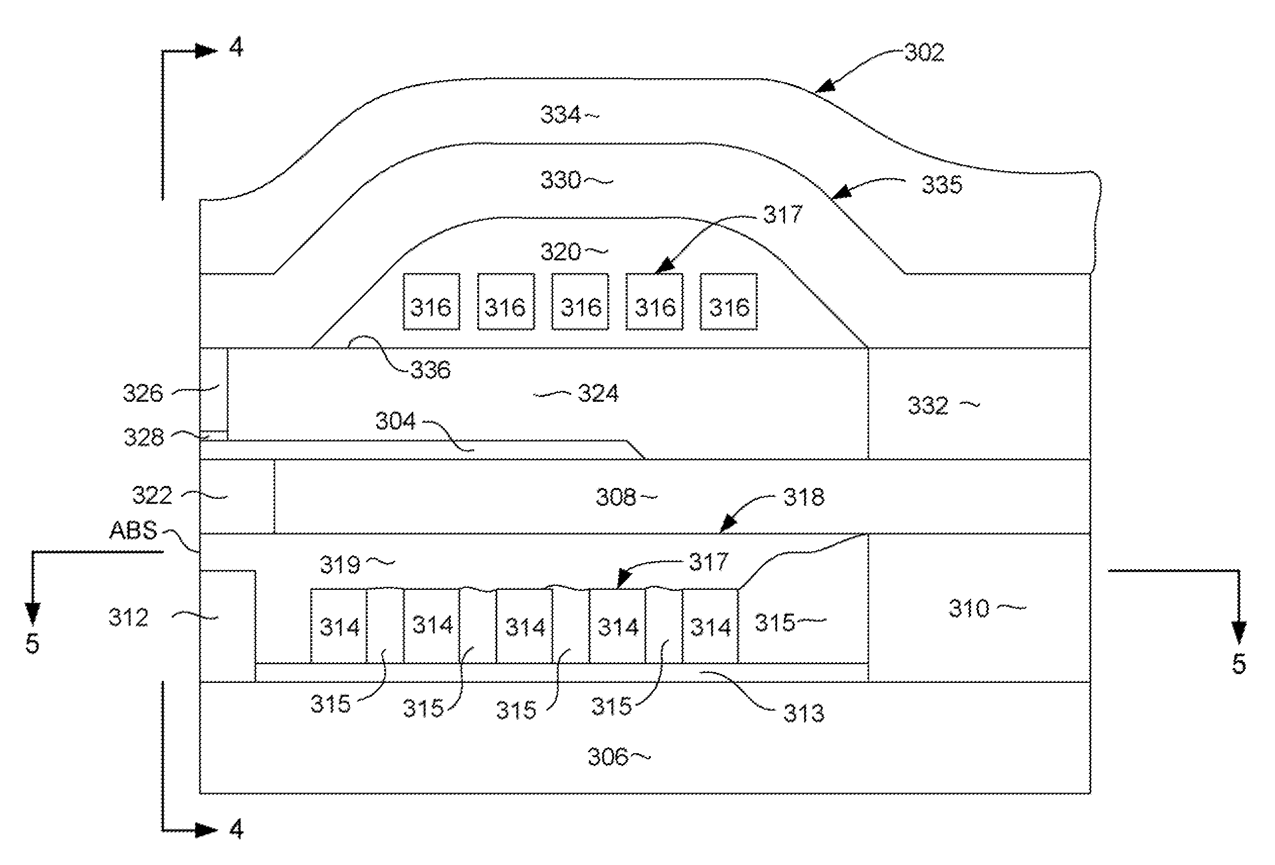
[0010]The present invention provides write head structure having a helical write coil that can be efficiently manufactured with minimal manufacturing complexity and with a minimum of manufacturing steps. The write head includes a write pole and a helical write coil having upper coil portions that pass above the write pole and lower coil portions that pass below the write pole. The upper and lower coil portions are electrically connected with another by connection studs. Whereas the upper and lower coil portions are constructed of a non-magnetic, electrically conductive material such as Cu, the connection studs are constructed of a magnetic, electrically conductive material such as NiFe.
[0011]By constructing the connection studs of a magnetic material, they can advantageously be constructed in the same manufacturing steps used to manufacture various magnetic structures of the write head, such as a magnetic shaping layer and / or the back gap. This greatly simplifies the manufacture of the write head by eliminating many additional manufacturing steps that would otherwise be required to manufacture a helical coil having non-magnetic connection studs.

Problems solved by technology

Such helical coils are however difficult to construct, because they are formed in a dimension that is perpendicular to the planes of the deposited layers.
This inherent manufacturing difficulty results in a great deal of added manufacturing complexity and cost.

Method used


Image

  • Magnetic write head with helical coil structure using multiple materials
  • Magnetic write head with helical coil structure using multiple materials
  • Magnetic write head with helical coil structure using multiple materials

Examples


Embodiment Construction

[0020]The following description is of the best embodiments presently contemplated for carrying out this invention. This description is made for the purpose of illustrating the general principles of this invention and is not meant to limit the inventive concepts claimed herein.

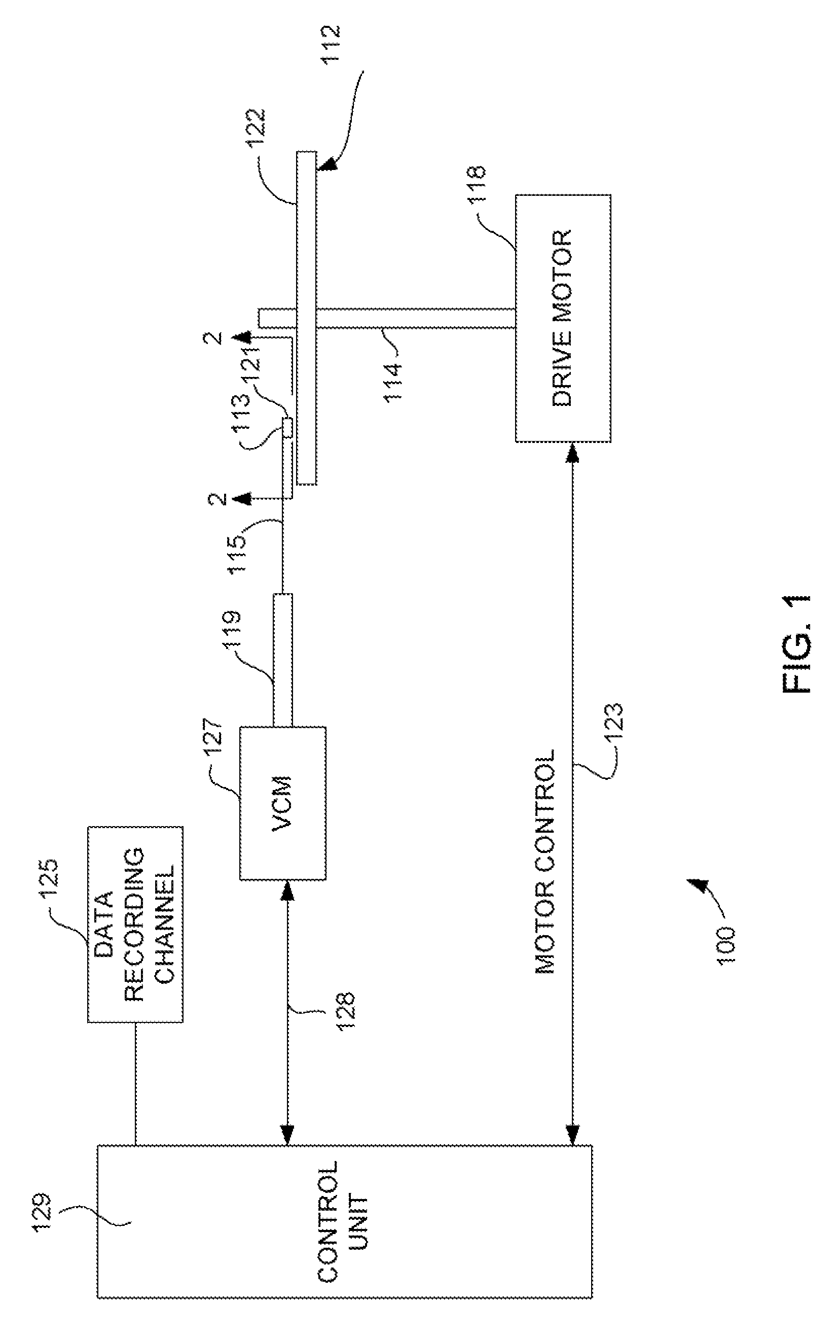
[0021]Referring now to FIG. 1, there is shown a disk drive 100 embodying this invention. A shown in FIG. 1, at least one rotatable magnetic disk 112 is supported on a spindle 114 and rotated by a disk drive motor 118. The magnetic recording on each disk is in the form of annular patterns of concentric data tracks (not shown) on the magnetic disk 112.

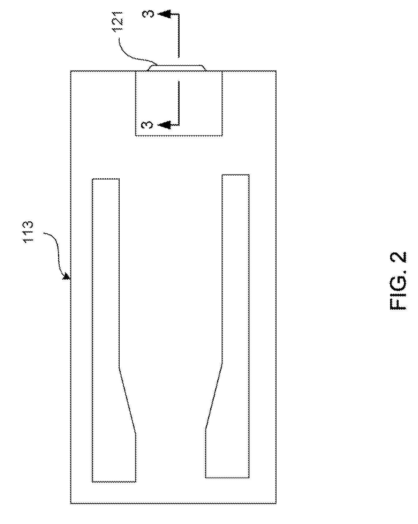
[0022]At least one slider 113 is positioned near the magnetic disk 112, each slider 113 supporting one or more magnetic head assemblies 221. As the magnetic disk rotates, slider 113 moves radially in and out over the disk surface 122 so that the magnetic head assembly 121 may access different tracks of the magnetic disk where desired data are written. Each slider 11...


PUM

PropertyMeasurementUnit
cycle timeaaaaaaaaaa
electrically conductiveaaaaaaaaaa
magneticaaaaaaaaaa

Abstract

A magnetic write head for perpendicular magnetic recording that has a helical coil design that reduces manufacturing complexity and increases cycle time for manufacture. The write head includes a write pole and a helical write coil having upper coil portions that pass above the write pole and lower coil portions that pass below the write pole. The upper and lower coil portions are connected with another by connection studs. Whereas the upper and lower coil portions are constructed of a non-magnetic, electrically conductive material such as Cu, the connection studs are constructed of a magnetic, electrically conductive material such as NiFe. By constructing the connection studs of a magnetic material, they can be constructed in the same manufacturing steps used to manufacture various magnetic structures of the write head, such as a magnetic shaping layer and / or the back gap. This greatly simplifies the manufacture of the write head by eliminating many additional manufacturing steps that would otherwise be required to manufacture a helical coil having non-magnetic connection studs.

Description

FIELD OF THE INVENTION[0001]The present invention relates to perpendicular magnetic recording and more particularly to a method for manufacturing a write head having a helical coil design that uses multiple materials for improved manufacturability.BACKGROUND OF THE INVENTION[0002]The heart of a computer's long term memory is an assembly that is referred to as a magnetic disk drive. The magnetic disk drive includes a rotating magnetic disk, write and read heads that are suspended by a suspension arm adjacent to a surface of the rotating magnetic disk and an actuator that swings the suspension arm to place the read and write heads over selected circular tracks on the rotating disk. The read and write heads are directly located on a slider that has an air bearing surface (ABS). The suspension arm biases the slider toward the surface of the disk, and when the disk rotates, air adjacent to the disk moves along with the surface of the disk. The slider flies over the surface of the disk on...

Claims


Application Information

Patent Timeline
Patent Type & Authority Patents(United States)
IPC IPC(8): G11B5/127
CPCG11B5/1278G11B5/315G11B5/3123G11B5/39G11B5/127
Inventor HSIAO, WEN-CHIEN DAVIDLEE, EDWARD HIN PONGLOO, JENNIFER AI-MING
Owner WESTERN DIGITAL TECH INC
Why Eureka
Try Eureka