Method for obtaining real ear measurements using a hearing aid

a technology of hearing aids and ear measurements, applied in hearing aid testing/monitoring, electrical equipment, medical science, etc., can solve the problem of not being able to make real ear measurements with only one microphone, and achieve the effect of improving the adaptation of hearing aids, improving comfort and benefit experience, and easy establishment of loudspeakers

Inactive Publication Date: 2009-12-15
OTICON
View PDF6 Cites 7 Cited by
  • Summary
  • Abstract
  • Description
  • Claims
  • Application Information

AI Technical Summary

Benefits of technology

[0007]By using the hearing aid microphone for the measurements and use the level meter which is already present in modem digital hearing aids it becomes possible to obtain data relating to the real ear wherein the hearing aid is going to function, and thus an easy way of improving the adaptation of the hearing aid to the individual is provided. The fact that the method can be used without further leads or connections and without expensive accessories will make this method more widely used, and in the end it will improve the comfort and benefit experienced by the end user of the hearing aid.
[0008]In an embodiment of the invention, the second end of the tube is placed near the microphone inlet of the hearing aid this being the reference point during the first time the sequence of steps is performed and further the second end of the tube is placed near the tympanic membrane during the second time the sequence of steps is performed. According to this embodiment, the ear canal is otherwise left open, and the sound signal at both the first and the second time the sequence of steps is performed is provided from a source outside the hearing aid. In this way an easy and straight forward way of obtaining REUG data is provided, where the dispenser uses a minimum of extra equipment namely the tube connecting the one microphone with the reference point and the area in front of the tympanic membrane respectively and a loudspeaker. The connection between the hearing aid and the fitting device is established anyhow and a program with the necessary alterations to handle the measurement and the loudspeaker is easily established. The difference between the two measurement results are not influenced by tube and external signal as long as the tube and the test signal are the same for both measurements. Thus more precise and accurate data on the REUG may be obtained when using the method according to the invention.
[0009]In a further embodiment the second end of the tube is connected to the inside volume of a coupler in a test box, this being the reference point, during the first time the sequence of steps is performed and the second end of the tube is placed near the tympanic membrane with the hearing aid or ear mould in place in the ear canal with possible venting canal blocked during the second time the sequence of steps is performed. The sound used for both the first and the second time the sequence of steps is performed is provided by the hearing aid receiver. According to this embodiment the invention allows RECD data to be obtained. In the cause of the first measurement in the coupler, the hearing aid is not connected to the fitting device, and the measurement data are stored inside a memory space in the hearing aid. The data is used after the second measurement, when the hearing aid is placed at the ear of the final user, and the same measurement is performed at the real ear. The difference between the two data sets allows a fine tuning of the hearing aid, which accounts for the difference between the response of the coupler and the response of the real ear of the user. All of this can essentially be gained with the simple tube connection between the hearing aid microphone and the surrounding along with simple fitting tool alterations to account for the extra measurement.
[0010]In a further embodiment the sequence of steps is performed once with the second end of the tube near the tympanic membrane, and with the hearing aid or ear mould in the ear. In this measurement the sound is generated by the hearing aid. This measurement can give an idea of the REAR, provided the microphone to receiver transfer function of the hearing aid is known. This transfer function or a good approximation thereof is usually easy to establish and thus the simple measurement can give a good estimate of the REAR response without having to provide extra measuring units and well controlled sound environments.

Problems solved by technology

With the prior art hearing aids and methods it is not possible to make real ear measurements with only one microphone.

Method used


Image

  • Method for obtaining real ear measurements using a hearing aid
  • Method for obtaining real ear measurements using a hearing aid
  • Method for obtaining real ear measurements using a hearing aid

Examples


Embodiment Construction

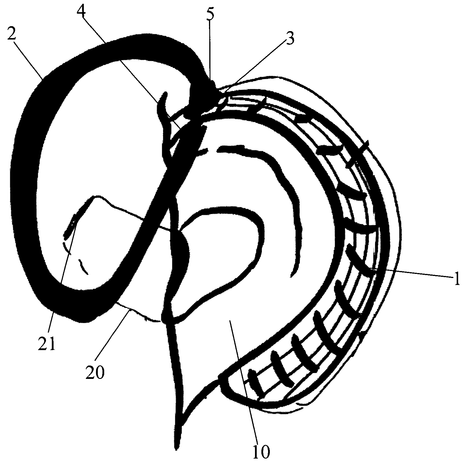
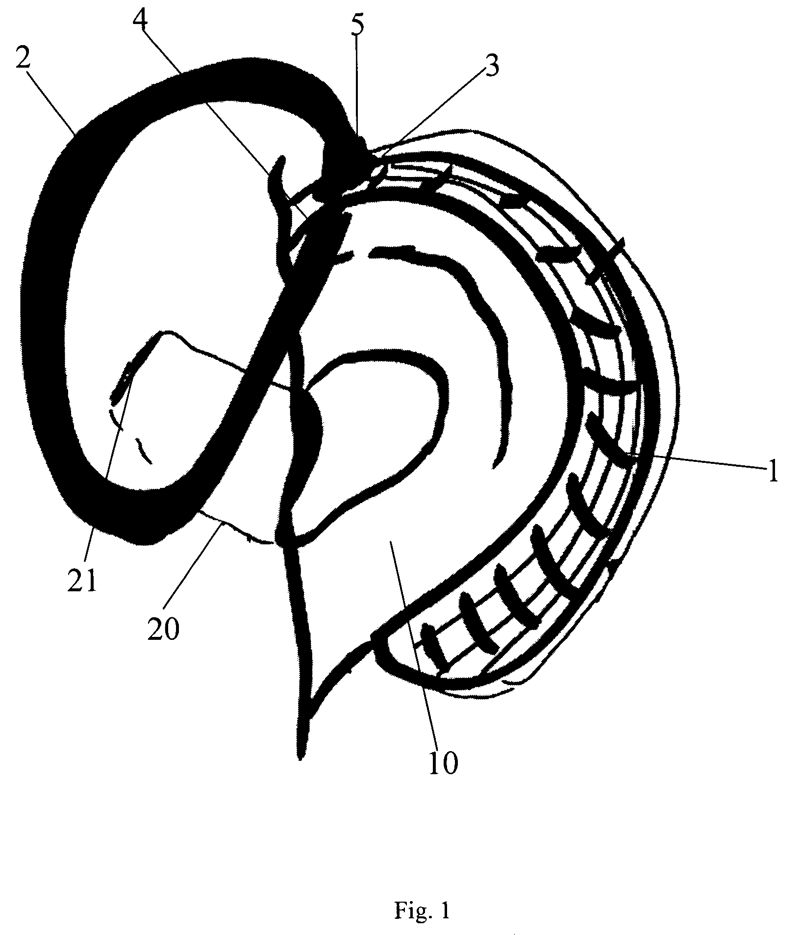
[0016]In a first aspect of the invention Real Ear Unaided Gain or REUG data is obtained using the hearing aid as the measuring instrument. To measure REUG, a sequential measurement in free field of an identical noise signal is required. As explained, prior art measurements are performed with dedicated microphones which at the same time samples sound from inside the ear, usually by use of a small tube placed inside the ear, and from a reference point outside the ear.

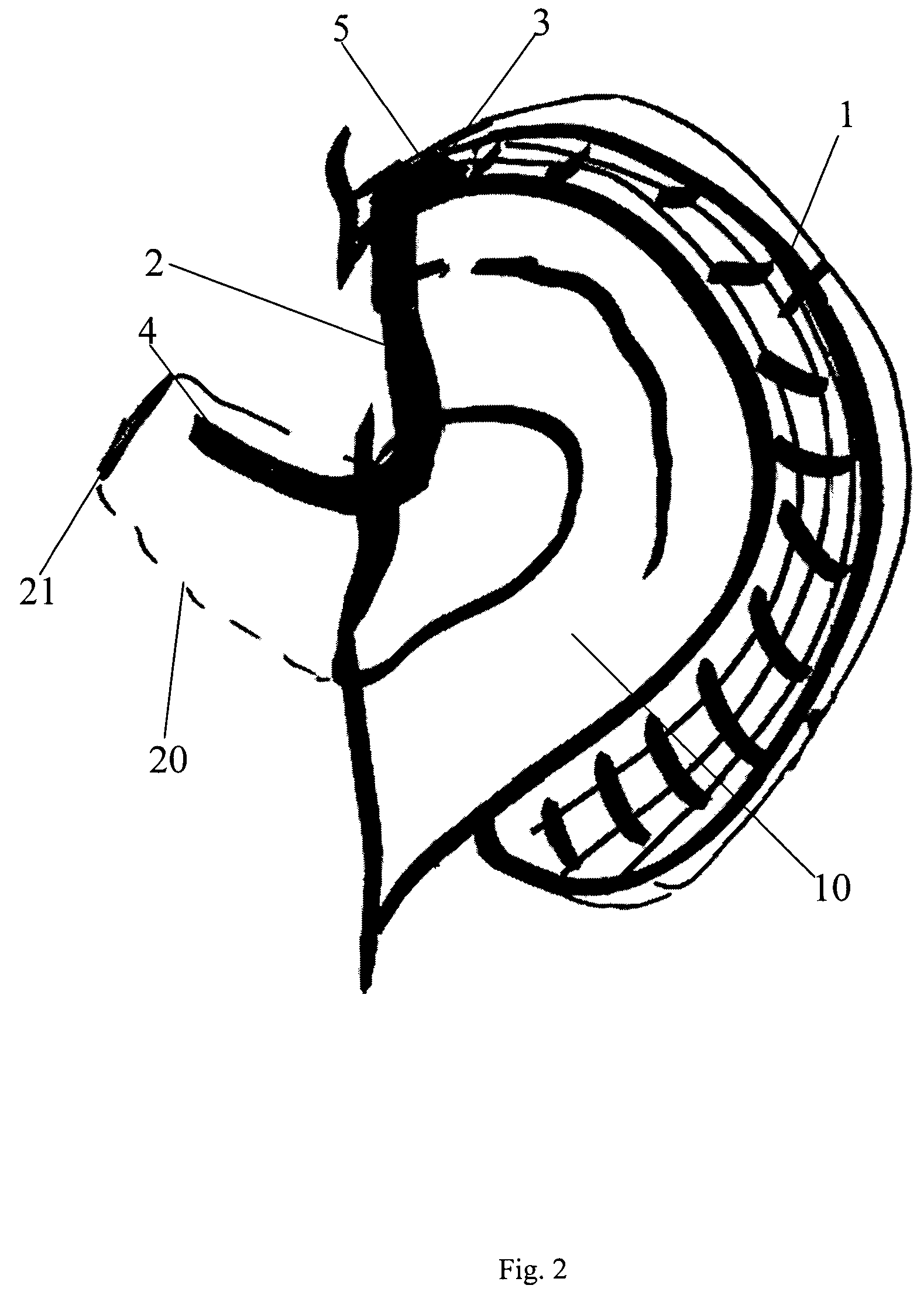
[0017]As shown in FIGS. 1 and 2 a sequential measurement is used according to the invention. The reference measurement outside the ear is illustrated in FIG. 1. Here a BTE (behind the ear hearing aid) 1 is placed at the ear 10. A tube 2 is connected at a first end 5 to the microphone inlet 3 of the BTE 1 and the other end 4 of the tube 2 is placed at the reference position. This reference position is right at the microphone inlet 3 of the BTE 1. The hearing aid 1 will be connected to a PC or other fitting device (not show...


PUM


Abstract

The invention regards a method for measuring audio response of a real ear using the microphone of a hearing aid of an end user. The following sequence of steps is performed: provide a sound tight connection between the hearing aid microphone and a first end of a soundguiding flexible tube, disable any further microphones in the hearing aid, place a second end of the tube at the location wherefrom sound is to be captured, provide an audio sound signal at the area of the second end of the tube and record the sound guided through the tube to the microphone of the hearing aid, process the recorded sounds to retrieve sound level values. Hereby real ear measurements may be gained with a hearing aid with only one microphone without any additional measuring equipment.

Description

AREA OF THE INVENTION[0001]The invention concerns the obtaining of data relating to the impact a hearing aid has on the sound pressure in front of the tympanic membrane when the hearing aid is producing sound.BACKGROUND OF THE INVENTION[0002]In prior art document U.S. Pat. No. 6,154,546 it is known to apply a tube connected to one of the microphones in a directional digital hearing aid with more than one microphone. According to the patent the probe tube is adapted to be fitted inside the ear of the patient and to convey sound signals there from to one of the microphones of the hearing aid. When this system is used, two microphones are necessary as one microphone is to sense the conditions in front of the tympanic membrane while the other microphone at the same time will record the sound level at the ear.[0003]From U.S. Pat. No. 6,118,877 it is further known to make use of a tone generator in the hearing aid to produce audio sounds for testing purposes.[0004]With the prior art heari...

Claims


Application Information

Patent Timeline
Patent Type & Authority Patents(United States)
IPC IPC(8): H04R25/00
CPCA61B5/12A61B5/6817H04R25/70H04R25/30
Inventor REBER, MONIKA BERTGES
Owner OTICON
Why Eureka
Try Eureka