Method and apparatus for machining workpieces having interruptions

a technology of interrupting cutting and workpieces, applied in the field of materials machining, can solve the problems of accelerated tool wear and failure, difficult machining operation of interrupting cutting, and higher impact force on the inser

Active Publication Date: 2009-12-22
AIR PROD & CHEM INC
View PDF120 Cites 49 Cited by
  • Summary
  • Abstract
  • Description
  • Claims
  • Application Information

AI Technical Summary

Benefits of technology

[0024]FIG. 10 is a graph illustrating tool life for various inserts and operating conditions.

Problems solved by technology

Interrupted cutting is a difficult machining operation, due to a shock-wave-type cyclic thermal and mechanical loading of the tool.
The use of the conventional flooding or jetting cooling medium, applied “externally” to the cutting tool and / or in the general area of contact between the tool and the work material results in cooling and hardening of the edges of the material interruptions, leading to higher impact forces on the insert, and thereby leads to accelerated tool wear and failure, usually by fractures.
The absence of cooling shortens the life of the cutting tool due to operation at high temperature involving thermal softening and chemical wear of the cutting edge as well as the rest of the insert.
The net result is that tool life is drastically shorter during interrupted cutting relative to non-interrupted cutting whether the cooling is used or not.

Method used


Image

  • Method and apparatus for machining workpieces having interruptions
  • Method and apparatus for machining workpieces having interruptions
  • Method and apparatus for machining workpieces having interruptions

Examples


example 1

Interrupted Cutting Using Dry Uncooled and Cooled Ceramic Insert

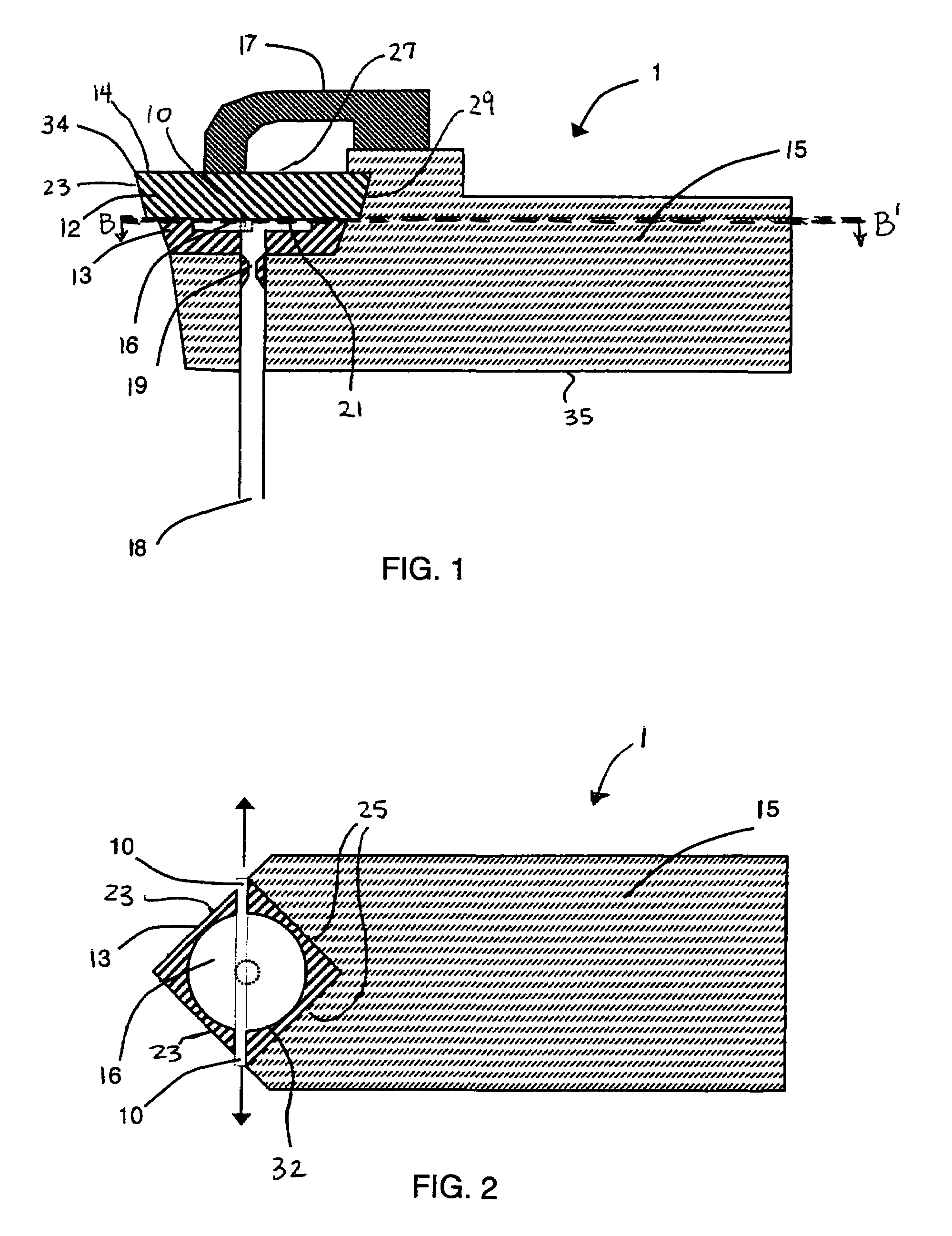
[0049]FIG. 9 shows flank wear versus the cutting time for relatively inexpensive alumina tools, so-called black ceramic (Al2O3) inserts under dry cutting conditions and with liquid nitrogen (LIN) cooling according to the current invention where the cooling passage was in the shim as illustrated in FIG. 1. The workpiece material was 52100 bearing steel (heat-treat hardened to 50-56 HRc). The interruption in the workpiece was a 3 / 16″ slot. The depth of cut was 0.007″, the feed rate was 0.005″ per revolution, and the speed was 1300 surface feet per minute, typical of hard turning industry conditions. The flank wear for dry cutting was significantly higher than with LIN cooling according to the current invention. Under dry cutting conditions, the insert chipped in about 2.25 minutes of operation, whereas with LIN cooling, the insert chipped in about 4.5 minutes. The tool life was extended about 100% using cooling according ...

example 2

Interrupted Cutting Using Dry and Flooded PCBN and Cooled Ceramic Insert

[0050]FIG. 10 presents data showing nose wear of the cutting insert versus the number of interruptions experienced for both dry and emulsion flooded cutting using a relatively expensive polycrystalline cubic boron nitride (PCBN) insert and cutting using an inexpensive alumina insert (ZC4) with LIN cooling according to the current invention. (The nose is part of the cutting insert and is indicated as 34 in FIG. 1.) PCBN inserts are generally recommended for interrupted machining operations. The depth of cut was 0.007″, the feed rate was 0.005″ per revolution, and the speed was 900 surface feet per minute, typical of hard turning industry conditions. The workpiece material was the same as in Example 1. The interruption in the workpiece was a 3 / 16″ slot. The PCBN insert had a longer tool life when used dry versus flooding with an emulsion, i.e. the conventional emulsified, lubricating cutting fluid, indicating that...


PUM

PropertyMeasurementUnit
pressure dropaaaaaaaaaa
pressureaaaaaaaaaa
resistanceaaaaaaaaaa

Abstract

This invention is a method and apparatus for cutting a workpiece which may have interruptions, with a cutting insert having a cutting edge, where the cutting insert is held in a tool holder and is optionally supported by a shim. Coolant, which may contain liquid nitrogen, is introduced through a passageway to a cooling passage located near the cutting edge. The cooling passage may be located either under, behind, or under and behind the cutting edge. Coolant impacts the wall surfaces of the cooling passage near the cutting edge where it is partly evaporated thereby cooling the cutting insert.

Description

[0001]This invention claims the benefit of provisional application U.S. Ser. No. 60 / 611,015 filed Sep. 16, 2004, incorporated herein by reference.BACKGROUND OF THE INVENTION[0002]The present invention relates to the machining of materials, and more particularly is a method and apparatus for increasing cutting tool life when machining materials with interruptions by cutting such as occurs in turning, facing, boring, milling, and drilling with cutting inserts.[0003]Interruptions can be simple voids or portions of material with significantly different resistance to cutting. When interruptions exist in a material, the cutting force intermittently drops to a fraction of the maximum cutting force as the cutting edge passes over the interruption, e.g. to less than 50% of the maximum cutting force. (For the case of a void, the cutting force will drop to zero.) The size of the interruption must be large enough relative to the curvature of the cutting edge in the feed plane in order for the t...

Claims


Application Information

Patent Timeline
Patent Type & Authority Patents(United States)
IPC IPC(8): B23B27/00B23B1/00
CPCB23B27/10B23C5/28B23Q11/1053B23B2205/16Y10S82/90Y10T82/10Y10S82/901B23B3/00
Inventor GHOSH, RANAJITZURECKI, ZBIGNIEWGRIMM, LANCE MICHAEL
Owner AIR PROD & CHEM INC
Why Eureka
Try Eureka