
Delivery system for long self-expanding stents

a delivery system and self-expanding technology, applied in the field of intravascular devices and methods, can solve the problems of relative cumbersomeness, and achieve the effect of convenient deploymen

Active Publication Date: 2009-12-22
MEDTRONIC VASCULAR INC
View PDF6 Cites 25 Cited by
  • Summary
  • Abstract
  • Description
  • Claims
  • Application Information

AI Technical Summary

Benefits of technology

This method allows for controlled initial deployment of stents with manual effort, followed by automatic completion using a spring, simplifying the process and reducing the effort required for deploying long stents, making it more efficient and user-friendly.

Problems solved by technology

To completely deploy the stent, the physician had to retract the sheath over the entire length of the stent, which was relatively cumbersome and typically required the use of both hands or repeated motion of the physician in the case of long self-expanding stents.

Method used


Image

  • Delivery system for long self-expanding stents
  • Delivery system for long self-expanding stents
  • Delivery system for long self-expanding stents

Examples


Embodiment Construction

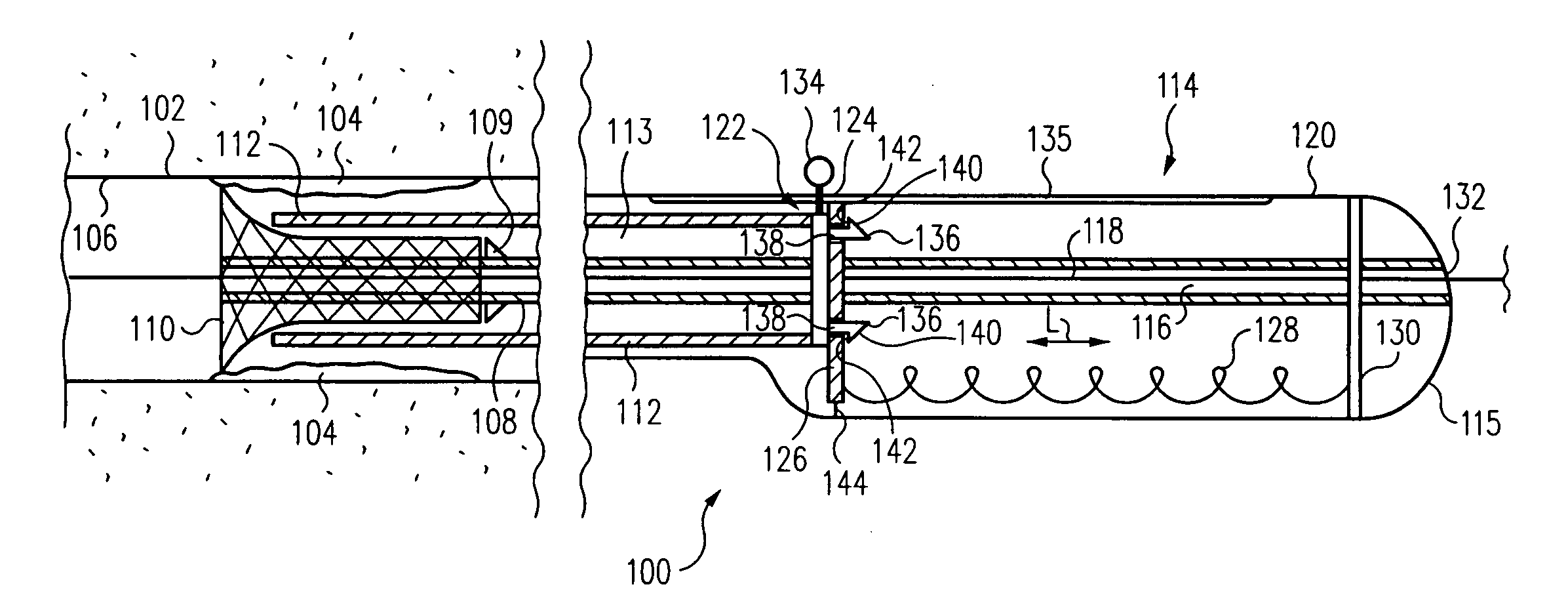
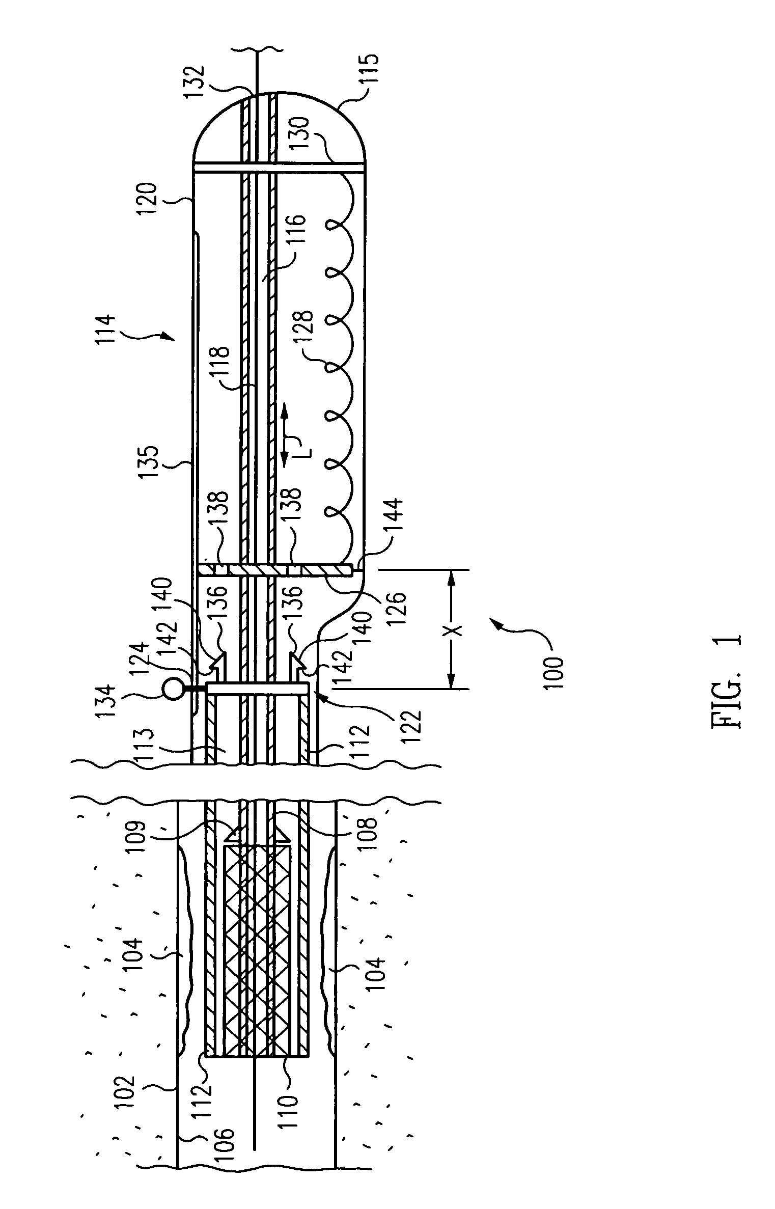
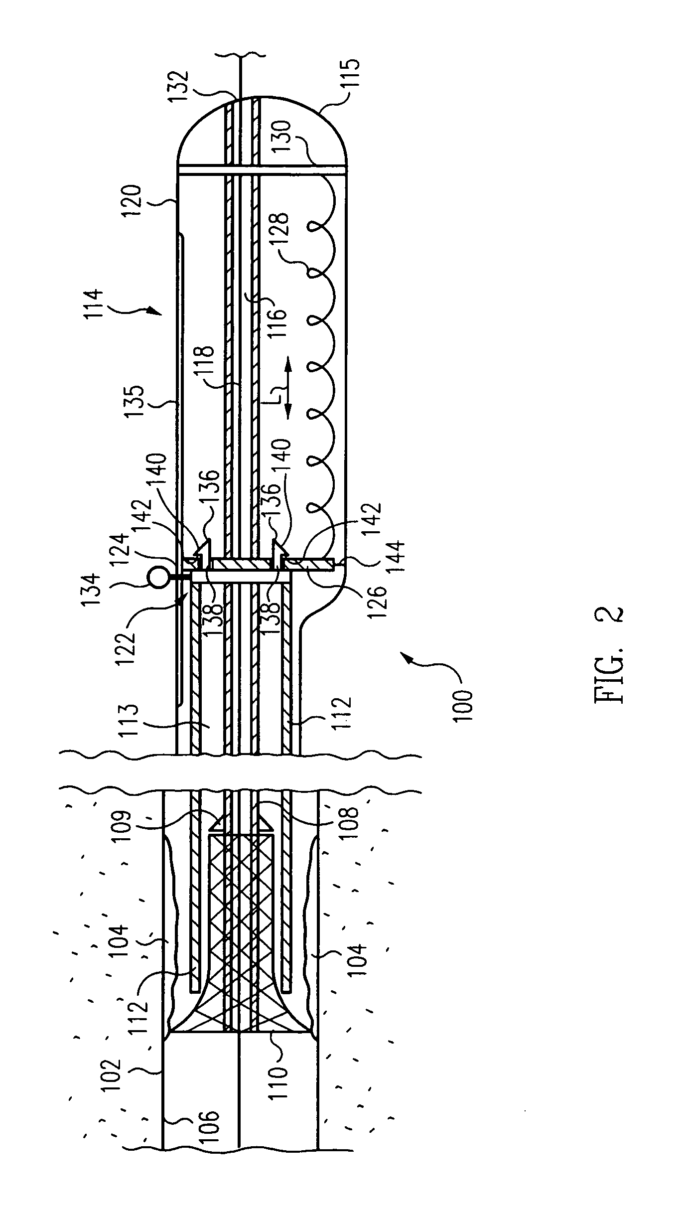
[0019]A method of deploying a stent 110 (FIG. 1) includes manually retracting a sheath 112, by moving an actuation button 134 on delivery handle 114 that is connected to sheath 112, to initiate deployment of stent 110, connecting a slider 122 coupled to sheath 112 to an engagement plate 126 (FIG. 2), and disengaging engagement plate 126 from a housing 120 (FIG. 3) to allow a spring 128 to retract engagement plate 126 and thus sheath 112 to automatically complete deployment of stent 110.

[0020]The method is well suited for use when stent 110 is long. More particularly, the initial deployment of stent 110 (FIGS. 1 and 2) is performed by the physician manually. This provides the physician with complete control of the initial deployment of stent 110. Further, once stent 110 is securely engaged within parent vessel 102, the remaining deployment over the remaining length of stent 110 (FIG. 3) is performed automatically by retraction of sheath 112 by spring 128. For shorter length stents th...


PUM


Abstract

The initial deployment of a self-expanding stent is performed by the physician manually retracting the sheath of a delivery system. This provides the physician with complete control of the initial deployment of the stent. Further, once the stent is securely engaged within the parent vessel, the remaining deployment over the remaining length of the stent is performed automatically by retraction of the sheath by a spring. Since the physician simply initiates the deployment of the stent, the deployment is readily performed using only a single hand of the physician.

Description

BACKGROUND OF THE INVENTION[0001]1. Field of the Invention[0002]The present invention relates to an intra-vascular device and method. More particularly, the present invention relates to a device for deployment of a stent for treatment of luminal, i.e., intra-vascular, diseases.[0003]2. Description of the Related Art[0004]In stent deployment systems, a self-expanding stent was restrained within a sheath. After positioning of the stent at the desired location via fluoroscopic guidance, the physician retracted the sheath to deploy the stent, i.e., to expose the stent and allow it to self-expand. To completely deploy the stent, the physician had to retract the sheath over the entire length of the stent, which was relatively cumbersome and typically required the use of both hands or repeated motion of the physician in the case of long self-expanding stents. Other devices required repeated motions such as ratcheting, using a thumbwheel or lever.SUMMARY OF THE INVENTION[0005]In one embodim...

Claims


Application Information

Patent Timeline
Patent Type & Authority Patents(United States)
IPC IPC(8): A61F2/06A61F2/84
CPCA61F2/95A61F2/966A61F2002/9517A61F2/9517
Inventor PRYOR, JACK D.
Owner MEDTRONIC VASCULAR INC
Learn More