Endoprosthesis for part of the pelvis

a technology for pelvis and endoprosthesis, applied in the field of endoprosthesis for part of the pelvis, to achieve the effect of increasing flexibility

Inactive Publication Date: 2009-12-22
ZIMMER GMBH
View PDF43 Cites 6 Cited by
  • Summary
  • Abstract
  • Description
  • Claims
  • Application Information

AI Technical Summary

Benefits of technology

[0006]It is therefore an underlying object of the present invention to provide an endoprosthesis for part of the pelvis of the initially named kind which is char

Problems solved by technology

It is, however, a disadvantage with the aforesaid endoprosthesis for part of the pelvis that the length of the spigot and the angular pos

Method used


Image

  • Endoprosthesis for part of the pelvis
  • Endoprosthesis for part of the pelvis
  • Endoprosthesis for part of the pelvis

Examples


Embodiment Construction

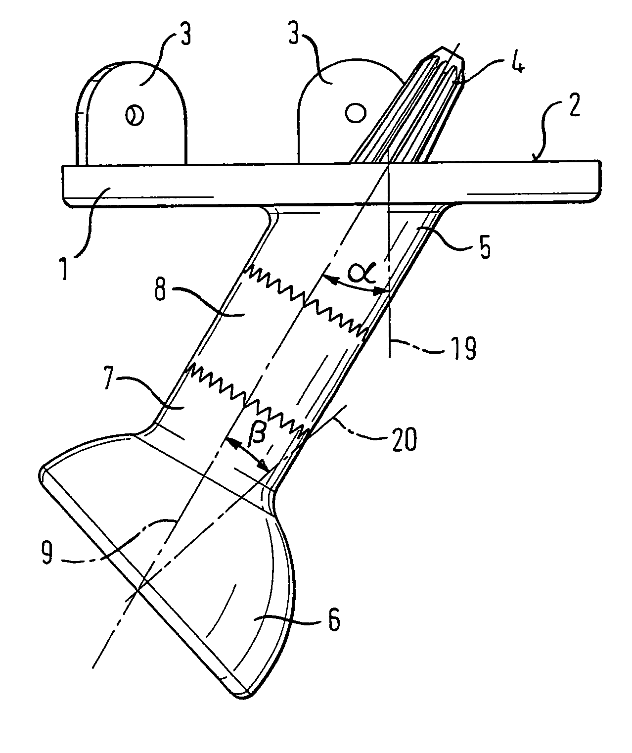
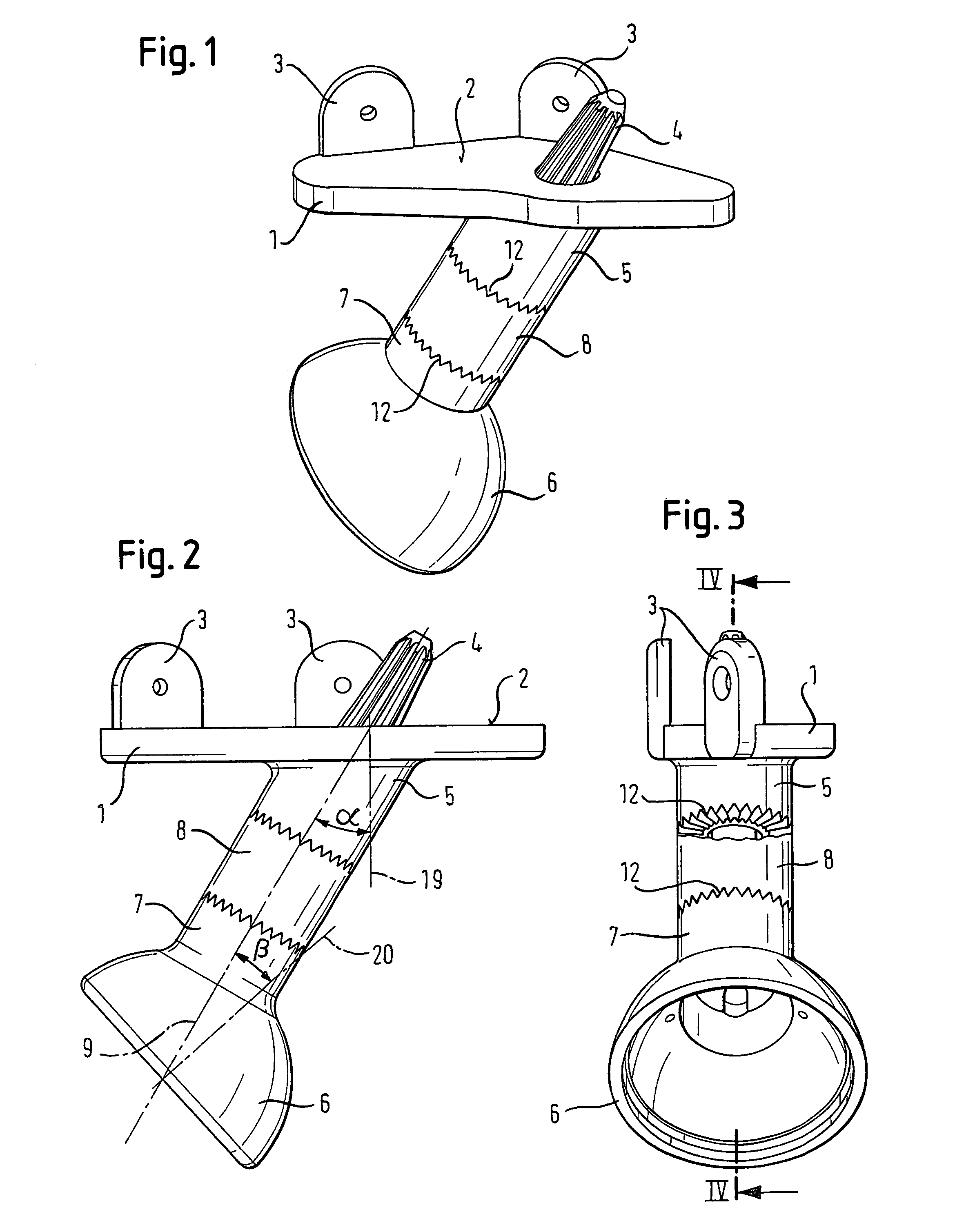
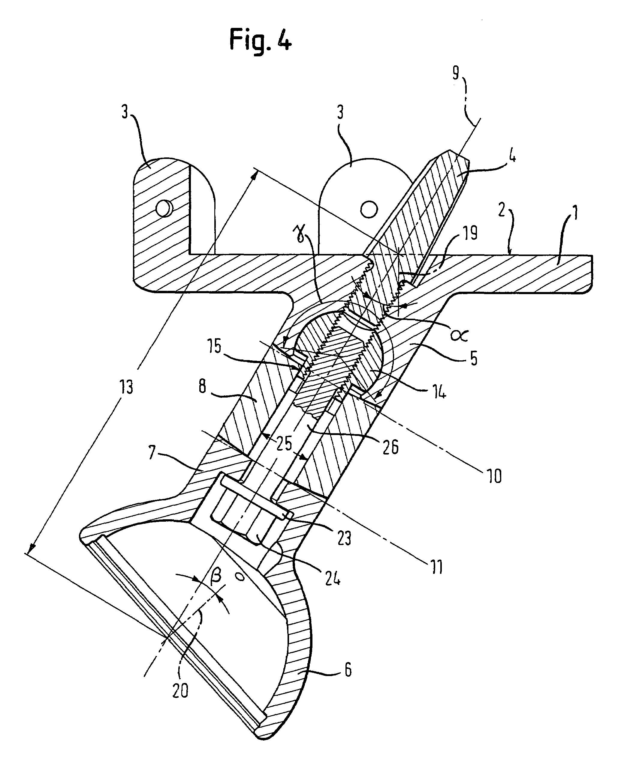
[0034]FIGS. 1, 2 and 3 show different views of an endoprosthesis for part of the pelvis in accordance with the invention shown in the assembled state for the replacement of a part of the pelvis in the region of the hip joint having a base element 1 which can be secured to a resected iliac bone, a hip shell 6 for the receiving of a hip joint ball and an intermediate element which is designed as a sleeve 8 and is arranged between the base element 1 and the hip shell 6.

[0035]A planar surface 2 of the base element 1 contacts the resection plane of the resected iliac bone (not shown). An anchoring spigot 4, which engages into a bore provided in the stub of the iliac bone, is inserted into the base element 1 to secure the base element 1 to the iliac bone.

[0036]The anchoring spigot 4 is inclined by an angle α with respect to an orthogonal 19 to the connection surface 2. The anchoring spigot 4 tapers conically at its end projecting beyond the connection surface 2 in the direction of the ili...


PUM


Abstract

The invention relates to an endoprosthesis for part of the pelvis having at least one base element which can be secured to a resected iliac bone and at least one hip shell attachable at a spacing thereto, with the base element having a first neck which in particular projects at an angle α from the orthogonal to a planar connection surface and the hip shell having a second neck which in particular projects at an angle β from its polar axis, with at least one separate intermediate element being provided which can be installed between the first neck and the second neck.

Description

BACKGROUND OF THE INVENTION[0001]The invention relates to an endoprosthesis for part of the pelvis having at least one base element which can be secured to a resected iliac bone and at least one hip shell attachable at a spacing thereto, with the base element having a first neck which in particular projects at an angle α from the orthogonal to a planar connection surface and the hip shell having a second neck which in particular projects at an angle β from its polar axis.[0002]There are some tumor patients where the ilium, i.e. half the pelvic bone, has to be resected from below by one-third to two-thirds of its height. Without further aid measures, it was previously customary to amputate the associated leg in order to avoid complications due to a lack of attachment to the trunk. To avoid such amputations, endoprostheses for part of the pelvis have been developed which may not be put under excessive strain, but which exert at least a passive retainer function for the leg attached to...

Claims


Application Information

Patent Timeline
IPC IPC(8): A61F2/36A61B17/80A61F2/00A61F2/02A61F2/30A61F2/32A61F2/34A61F2/46
CPCA61B17/8066A61F2/30749A61F2/34A61F2/30721A61F2250/0097A61F2/32A61F2/4684A61F2002/30143A61F2002/30154A61F2002/30235A61F2002/30367A61F2002/30377A61F2002/30378A61F2002/30405A61F2002/30433A61F2002/30434A61F2002/30494A61F2002/30509A61F2002/30533A61F2002/30538A61F2002/30551A61F2002/30578A61F2002/30599A61F2002/30604A61F2002/30616A61F2002/30617A61F2002/30652A61F2002/3071A61F2002/30774A61F2002/30794A61F2002/30827A61F2002/30878A61F2002/30879A61F2002/30891A61F2002/3241A61F2002/3411A61F2002/3414A61F2002/3611A61F2002/4638A61F2220/0025A61F2220/0033A61F2220/0041A61F2230/0017A61F2230/0021A61F2230/0069A61F2250/0006A61F2250/0063A61F2250/0085A61F2002/3053A61F2002/30507A61F2002/3055A61F2002/305A61F2002/3079
Inventor KARRER, DAVIDGROSS, WALTER
Owner ZIMMER GMBH
Why Eureka
Try Eureka