Supercharge Your Innovation With Domain-Expert AI Agents!

Communication control system and communication control method

a communication control system and control method technology, applied in the field of communication control system and communication control method, can solve the problems of low reliability, ineffective network performance, and inability to transmit data at an appropriate speed for each lin

Inactive Publication Date: 2009-12-22
FUJITSU LTD
View PDF16 Cites 2 Cited by
  • Summary
  • Abstract
  • Description
  • Claims
  • Application Information

AI Technical Summary

Problems solved by technology

The demand for the amounts of data that is passed through a network is increasing more and more with development of a computer network, but performance of the network cannot be made effective use of, according to the nature of a Transmission Control Protocol (TCP) which is a standard protocol for the network.
A User Datagram Protocol (UDP) has an advantage being a high transmission rate and a disadvantage being low reliability.
Therefore, changes in congestion situations, for example, the identical line is used by another communication, cannot be detected, and hence, data cannot be transmitted at an appropriate speed for each line.
This restricts data communication by the TCP packets.
In the conventional technology, however, a calculation equation (e.g., calculation algorism for an optimal packet transmission speed) used to perform the congestion control is complicated, or packets need to be periodically transmitted at an extremely short period.
Therefore, a heavy load can be exerted on a computer with non-real-time operating system (OS).
That is, in a network communication, if data exceeding the capacity (speed) of a communication channel passes through a channel, an excess of the data (packet) can be lost.
However, in order to periodically transmit a packet at an extremely short period based on the non-real-time OS, there is only one method of using a loop instruction or issuing an interrupt instruction at an accurate interval using specific hardware.
Thus, the calculation capacity is inevitably occupied by implementation of the congestion control.

Method used


Image

  • Communication control system and communication control method
  • Communication control system and communication control method
  • Communication control system and communication control method

Examples


Embodiment Construction

[0025]Exemplary embodiments of the case where a transmitting device and a receiving device in the communication control system are used for an information processor are explained in detail below with reference to the accompanying drawings. The overview and features of the communication control system according to the present invention are explained first, and then a communication control system according to a first embodiment is explained, and lastly, various modifications (second embodiment) as another embodiment are explained. In the first embodiment, an information processor on the data transmission side is described as “transmission-side terminal”, and an information processor on the data reception side is described as “reception-side terminal”.

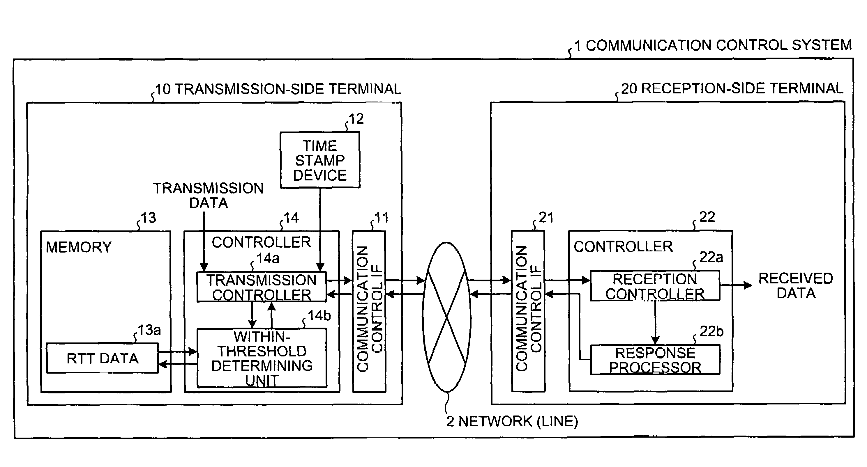
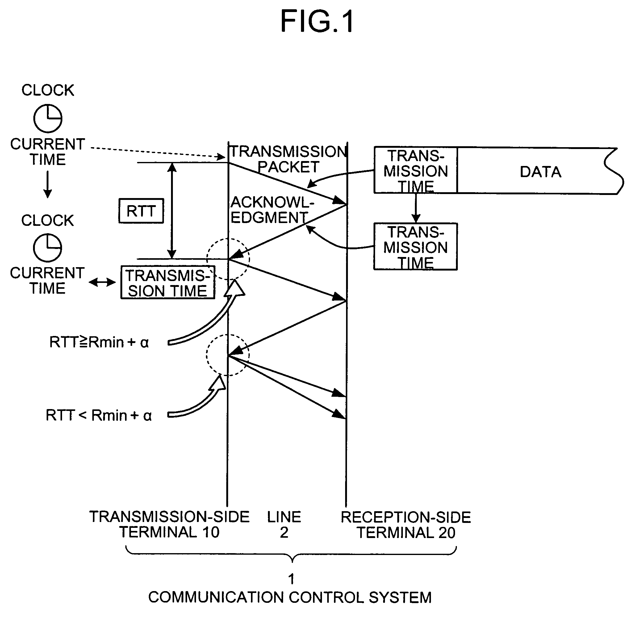
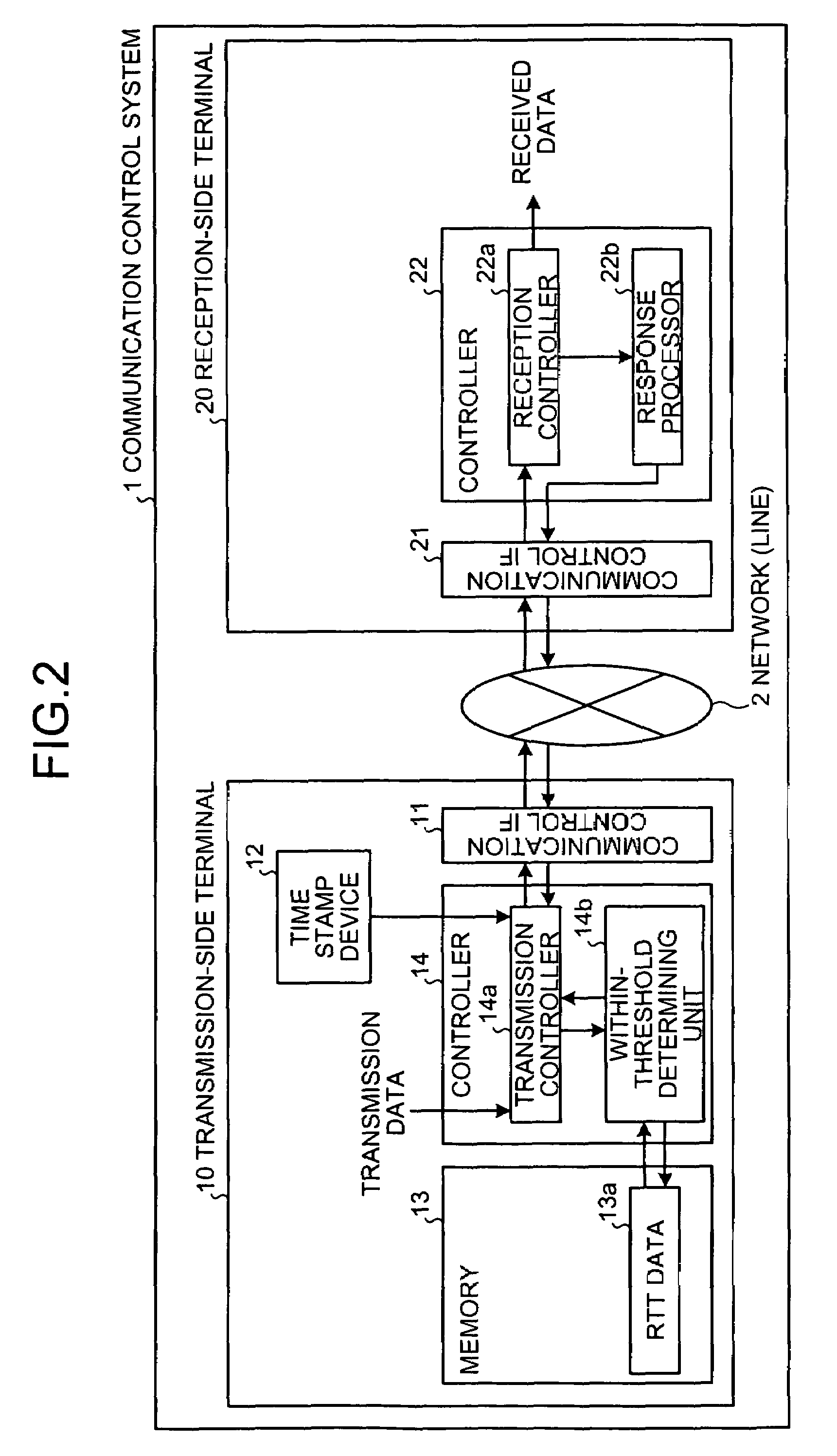
[0026]FIG. 1 is a conceptual diagram of the overview and features of an exemplary communication control system according to the present invention. A communication control system 1 controls UDP packet communication between a transmission-s...


PUM


Abstract

In a communication control system a reception-side terminal sends back transmission time information included in a transmission packet as an acknowledgment to a transmission-side terminal. The transmission-side terminal determines whether a response time, obtained from the transmission time information, is shorter than a threshold. When the response time is shorter, the transmission-side terminal controls so as to transmit to the reception-side terminal a larger number of packets than the number of packets upon transmission of the transmission packet, or to transmit the same number of packets as the number of packets upon transmission of the transmission packet.

Description

BACKGROUND OF THE INVENTION[0001]1. Field of the Invention[0002]The present invention relates to a technology for performing digital communications with packets.[0003]2. Description of the Related Art[0004]The demand for the amounts of data that is passed through a network is increasing more and more with development of a computer network, but performance of the network cannot be made effective use of, according to the nature of a Transmission Control Protocol (TCP) which is a standard protocol for the network.[0005]For this reason, Random Parity Stream (RPS) codes have been proposed. A User Datagram Protocol (UDP) has an advantage being a high transmission rate and a disadvantage being low reliability. In order to cover the disadvantage when transmission data is sent by a UDP packet, the RPS codes are used so that the low reliability is covered with Forward Error Correction (FEC).[0006]In UDP packet communication, a technique of sending UDP packets at intervals according to the siz...

Claims


Application Information

Patent Timeline
Patent Type & Authority Patents(United States)
IPC IPC(8): H04L12/26H04L12/841H04L12/911H04L12/801H04L29/08
CPCH04L1/1678H04L69/163H04L47/283H04L47/10H04L1/0002H04L69/16
Inventor SENTA, YOSUKESAZAWA, SHINICHISATO, YUICHI
Owner FUJITSU LTD
Features
  • R&D
  • Intellectual Property
  • Life Sciences
  • Materials
  • Tech Scout
  • Unparalleled Data Quality
  • Higher Quality Content
  • 60% Fewer Hallucinations
Learn More