Liquid ejection head, method of manufacturing same, and image forming apparatus

a technology of liquid ejection and manufacturing method, which is applied in the direction of inking apparatus, photomechanical apparatus, instruments, etc., can solve the problems of obstructing the movement of piezoelectric elements, unable to provide space for preventing obstruction of piezoelectric element movement, and unable to increase the density of wiring, etc., to achieve the effect of increasing the displacement of piezoelectric elements

Inactive Publication Date: 2009-12-29
FUJIFILM CORP
View PDF4 Cites 3 Cited by
  • Summary
  • Abstract
  • Description
  • Claims
  • Application Information

AI Technical Summary

Benefits of technology

[0015]The present invention has been contrived in view of the foregoing circumstances, an object thereof being to provide a liquid ejection head, a method of manufacturing same, and an image forming apparatus, whereby reliable wiring can be formed to the electrodes of piezoelectric elements, via through holes provided above the piezoelectric elements, even if spaces for preventing obstruction of the movement of piezoelectric elements driven in a bending vibration mode are provided above the piezoelectric elements, and whereby the wires inside the through holes can be formed together in one operation, without obstructing the movement of the piezoelectric elements, even if a conductive material having fluid characteristics is used to form the wires.

Problems solved by technology

It is difficult to increase the density of the wiring, by means of a one-dimensional or a two-dimensional wiring arrangement in which the wires are extended in a horizontal direction, and hence it is necessary to adopt a three-dimensional wiring arrangement using through holes, for example.
On the other hand, when using piezoelectric elements operating in the bending vibration mode, if the piezoelectric elements adhere tightly to the fixed plate, then it is not possible for the piezoelectric elements to bend, and therefore, a space which allows the piezoelectric elements to bend must be ensured on the opposite side of the piezoelectric elements from the diaphragm (namely, a space which prevents obstruction of the movement of the piezoelectric elements).
However, in the head described in Japanese Patent Application Publication No. 2001-113700, the electrical connections to the piezoelectric elements are made via through holes provided in the head substrate directly below the piezoelectric elements, but no consideration is given to providing spaces for preventing obstruction of the movement of the piezoelectric elements, as required when piezoelectric elements operating in the bending vibration mode are used as described above.
If piezoelectric elements operating in the bending vibration mode are used, then a problem arises when it is sought to make the electrical connections via these through holes.
For example, when the electrodes of the piezoelectric elements are connected to the wires via through holes, then if a semi-fluid material, such as solder, conductive paste, or the like, is used, the semi-fluid material may be project beyond the region where it is originally required, inside the hermetically sealed space, and hence there is a risk that this projecting material may obstruct the movement of the piezoelectric elements.
Furthermore, since the electrical connections are made within a hermetically sealed space, it is not possible to confirm the connection status, and there is a risk of connection defects.

Method used


Image

  • Liquid ejection head, method of manufacturing same, and image forming apparatus
  • Liquid ejection head, method of manufacturing same, and image forming apparatus
  • Liquid ejection head, method of manufacturing same, and image forming apparatus

Examples


first embodiment

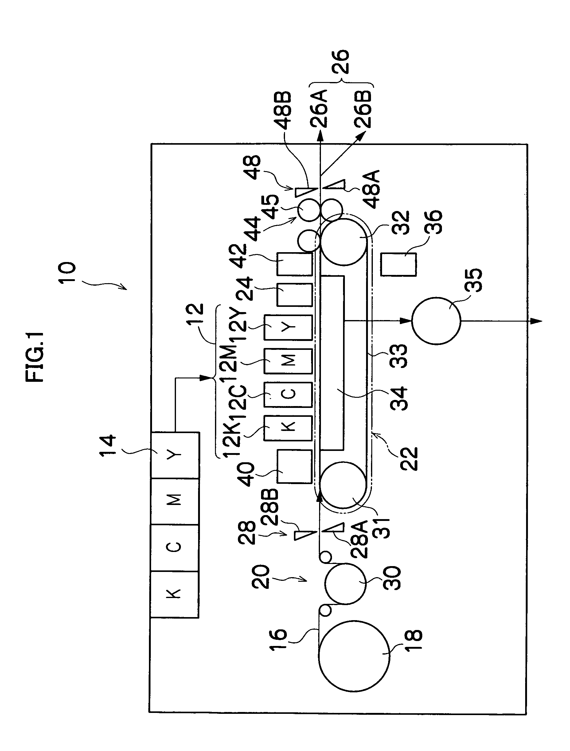
[0040]FIG. 1 is a general schematic drawing showing an approximate view of an inkjet recording apparatus forming an image forming apparatus having a liquid ejection head according to the present invention.

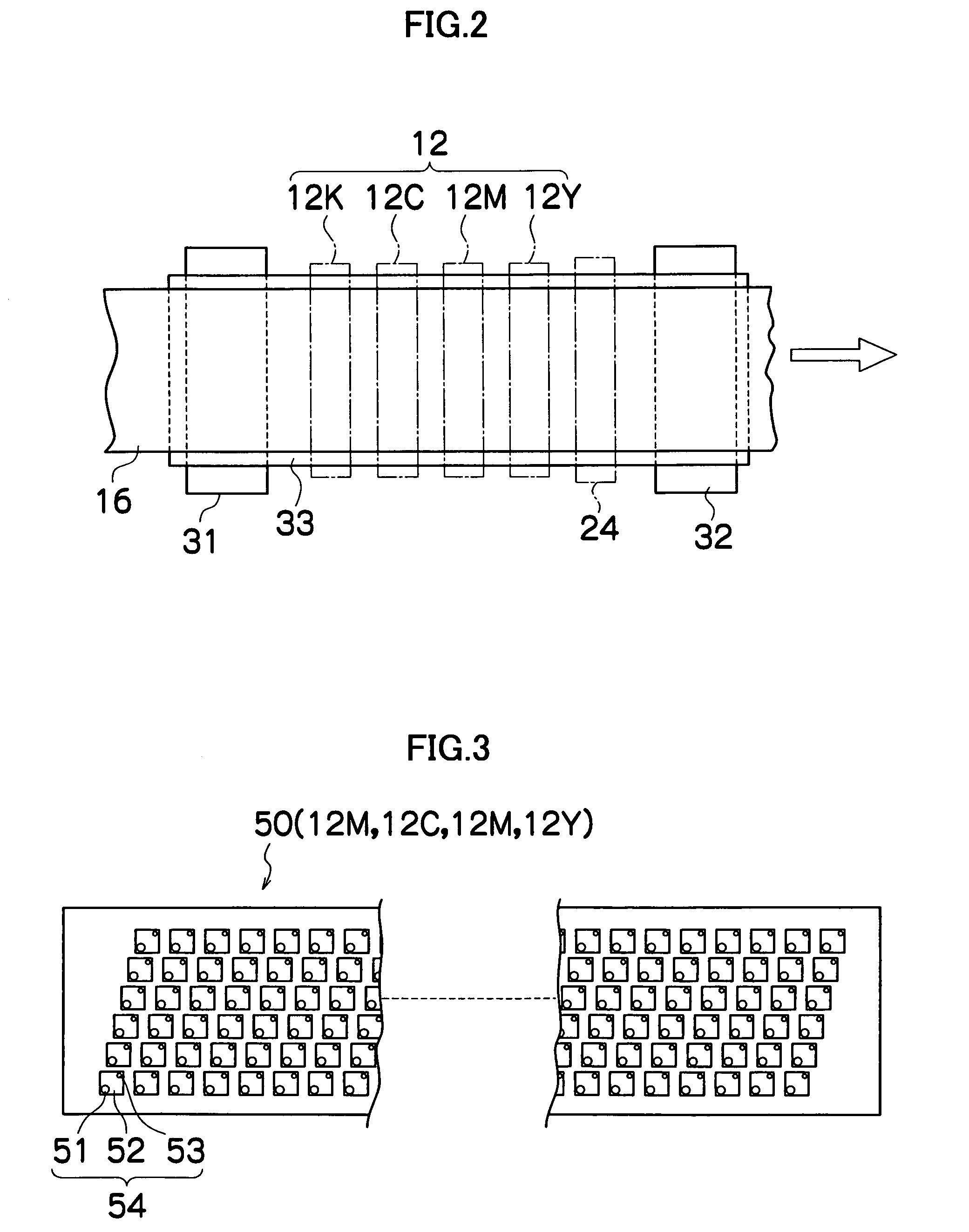
[0041]As shown in FIG. 1, the inkjet recording apparatus 10 comprises: a print unit 12 having a plurality of print heads 12K, 12C, 12M, and 12Y for ink colors of black (K), cyan (C), magenta (M), and yellow (Y), respectively; an ink storing and loading unit 14 for storing inks of K, C, M and Y to be supplied to the print heads 12K, 12C, 12M, and 12Y; a paper supply unit 18 for supplying recording paper 16; a decurling unit 20 for removing curl in the recording paper 16 supplied from the paper supply unit 18; a belt conveyance unit 22 disposed facing the nozzle face (ink-droplet ejection face) of the print unit 12, for conveying the recording paper 16 while keeping the recording paper 16 flat; a print determination unit 24 for reading the printed result produced by the print unit 12...

second embodiment

[0122]Next, the method of manufacturing a print head 50 according to the present invention is described.

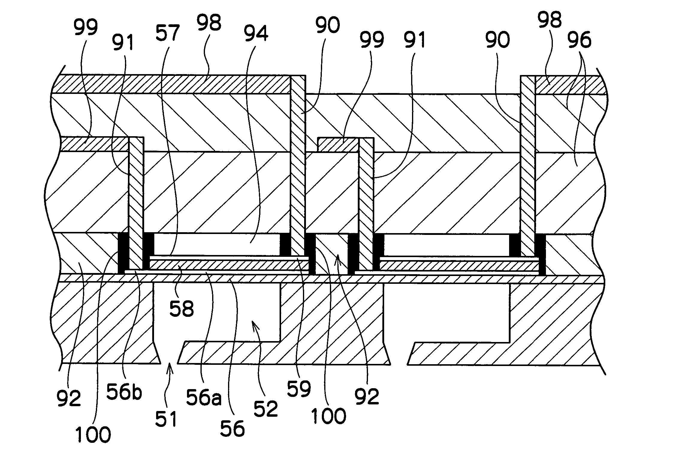
[0123]In the present embodiment, the piezoelectric body covers 92 for forming spaces that prevent obstruction of the movement of the piezoelectric bodies 58, and the portions which cover the bonding sections between the drive wires 90 and the wire connection sections 59, are formed in an integrated fashion.

[0124]FIGS. 10A to 10D show the sequence of steps in the method of manufacturing a print head according to the present embodiment.

[0125]Firstly, as shown in FIG. 10A, pressure chambers 52 connected to nozzles 51 and an ink supply channel (not shown), and a diaphragm 56 forming the ceiling of the pressure chambers 52 are formed, whereupon piezoelectric bodies 58 and individual electrodes 57 are formed on the diaphragm 56 in the regions corresponding to the pressure chambers 52, and a positive-type photosensitive resin 102 is applied over same. The photosensitive resin 102 is appl...


PUM

PropertyMeasurementUnit
diameteraaaaaaaaaa
photosensitiveaaaaaaaaaa
liquid ejection headaaaaaaaaaa

Abstract

The method manufactures a liquid ejection head having a diaphragm which forms a portion of pressure chambers connected to nozzles ejecting liquid, and piezoelectric elements which deform the diaphragm. The method includes the steps of: applying a photosensitive resin on at least a portion of each of electrodes of the piezoelectric elements; bonding a substrate having through holes, to the photosensitive resin; exposing the photosensitive resin via the through holes; developing the exposed photosensitive resin, thereby forming holes connecting to the through holes in the photosensitive resin; and filling conductive material into the through holes and the holes formed in the photosensitive resin.

Description

BACKGROUND OF THE INVENTION[0001]1. Field of the Invention[0002]The present invention relates to a liquid ejection head, a method of manufacturing same, and an image forming apparatus, and more particularly to a liquid ejection head, a method of manufacturing same and an image forming apparatus, in which connections for drive wires which supply drive signals to piezoelectric elements are devised, in a liquid ejection head using the piezoelectric elements as pressure generating devices for ejecting liquid.[0003]2. Description of the Related Art[0004]As an image forming apparatus, an inkjet printer (inkjet recording apparatus) is known, which comprises an inkjet head (liquid ejection head) having an arrangement of a plurality of nozzles (ejection ports) for ejecting ink (liquid) and which forms images on a recording medium by ejecting ink from the nozzles toward the recording medium, while causing the inkjet head and the recording medium to move relatively to each other.[0005]For exam...

Claims


Application Information

Patent Timeline
Patent Type & Authority Patents(United States)
IPC IPC(8): B41J2/045G03F1/00H01L21/00B41J2/055B41J2/135B41J2/14B41J2/145B41J2/155B41J2/16H01L41/09H01L41/22H01L41/29H01L41/313
CPCB41J2/14233B41J2/161B41J2/1623B41J2/1631B41J2/1639B41J2202/21B41J2002/14241B41J2002/14459B41J2002/14491B41J2202/18
Inventor OTA, HIROSHI
Owner FUJIFILM CORP
Why Eureka
Try Eureka