Wiring module

Active Publication Date: 2014-01-16
AUTONETWORKS TECH LTD +2
View PDF10 Cites 2 Cited by
  • Summary
  • Abstract
  • Description
  • Claims
  • Application Information

AI Technical Summary

Benefits of technology

[0016]Further, if the above wire accommodating passage is formed on the positioning member, the wires of the wiring harness accommodated in the wire accommodating passage can be easily bundled by the bundling member by forming the bundling member insertion hole on the outer wall of the wire accommodating passage.
[0017]Further, if the positioning member includes the positioning portions to be engaged with two or more positioned portions provided on each unit constituting the stacked device, the positioning member is positioned with respect to each unit. If the positioning member is mounted based on two or more p

Problems solved by technology

However, such as in the case of a stacked device formed by stacking identical units, a connector other than a corresponding one may be fitted to a certain unit constituting the stacke

Method used


Image

  • Wiring module
  • Wiring module
  • Wiring module

Examples


Embodiment Construction

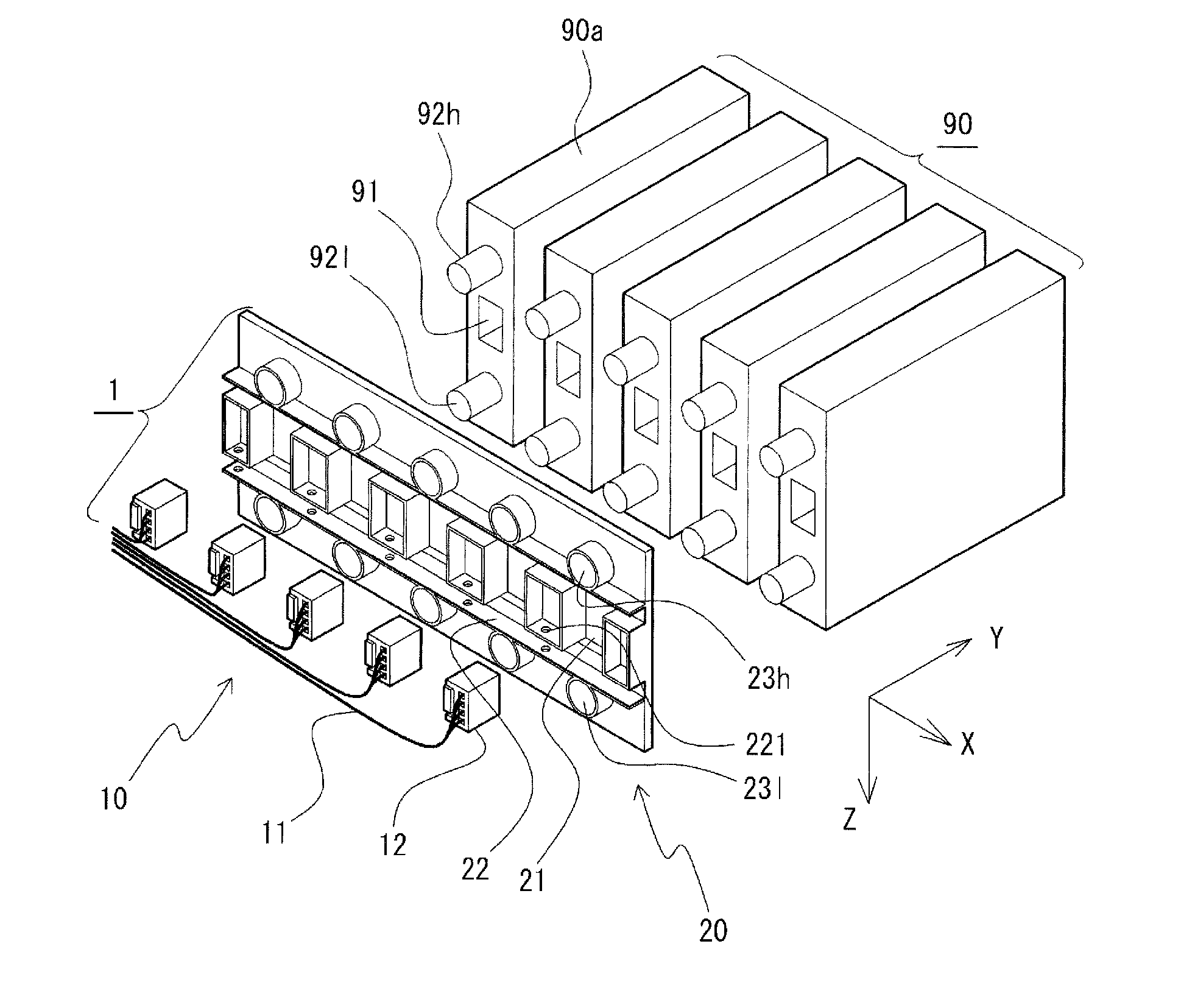
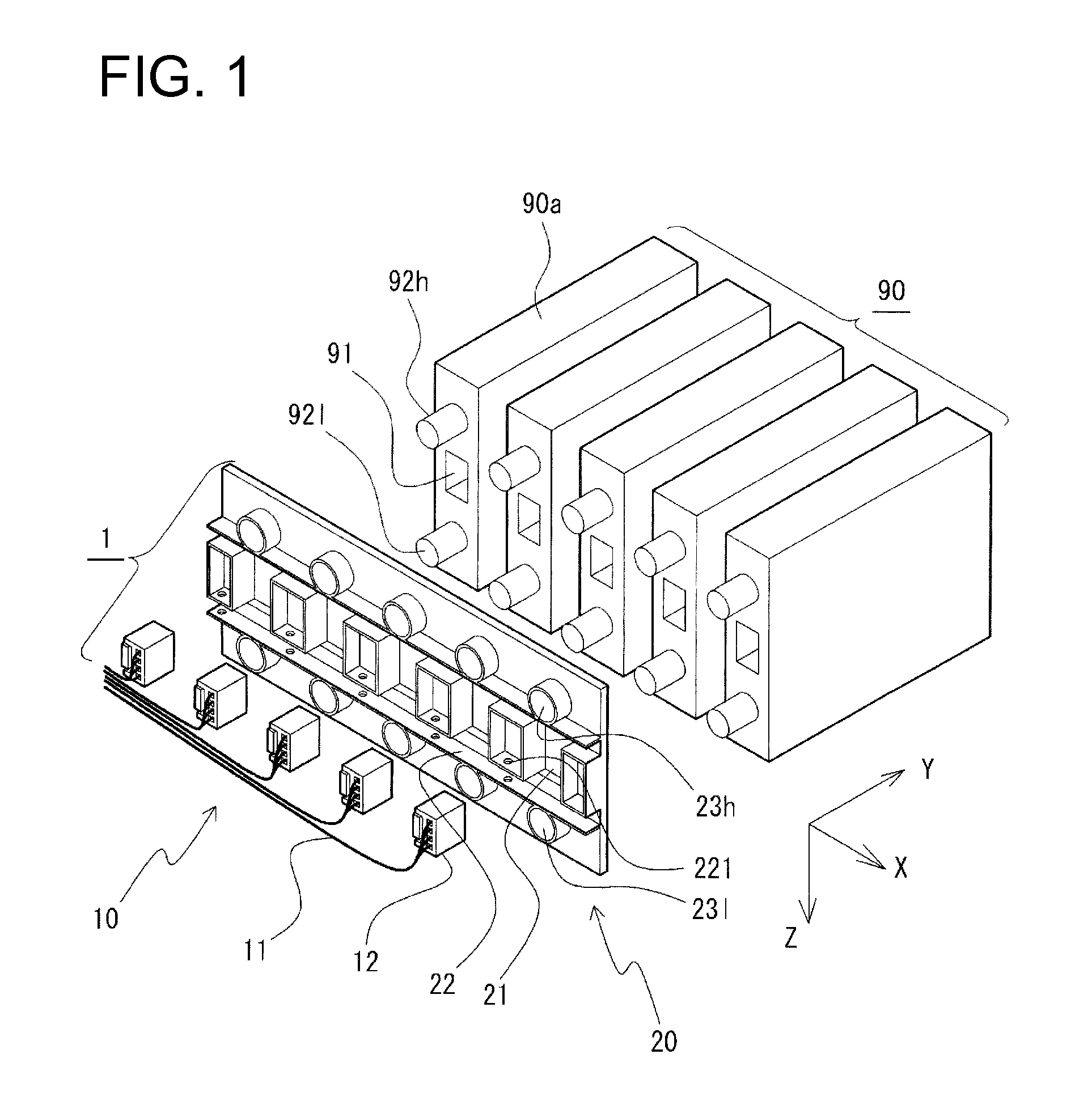
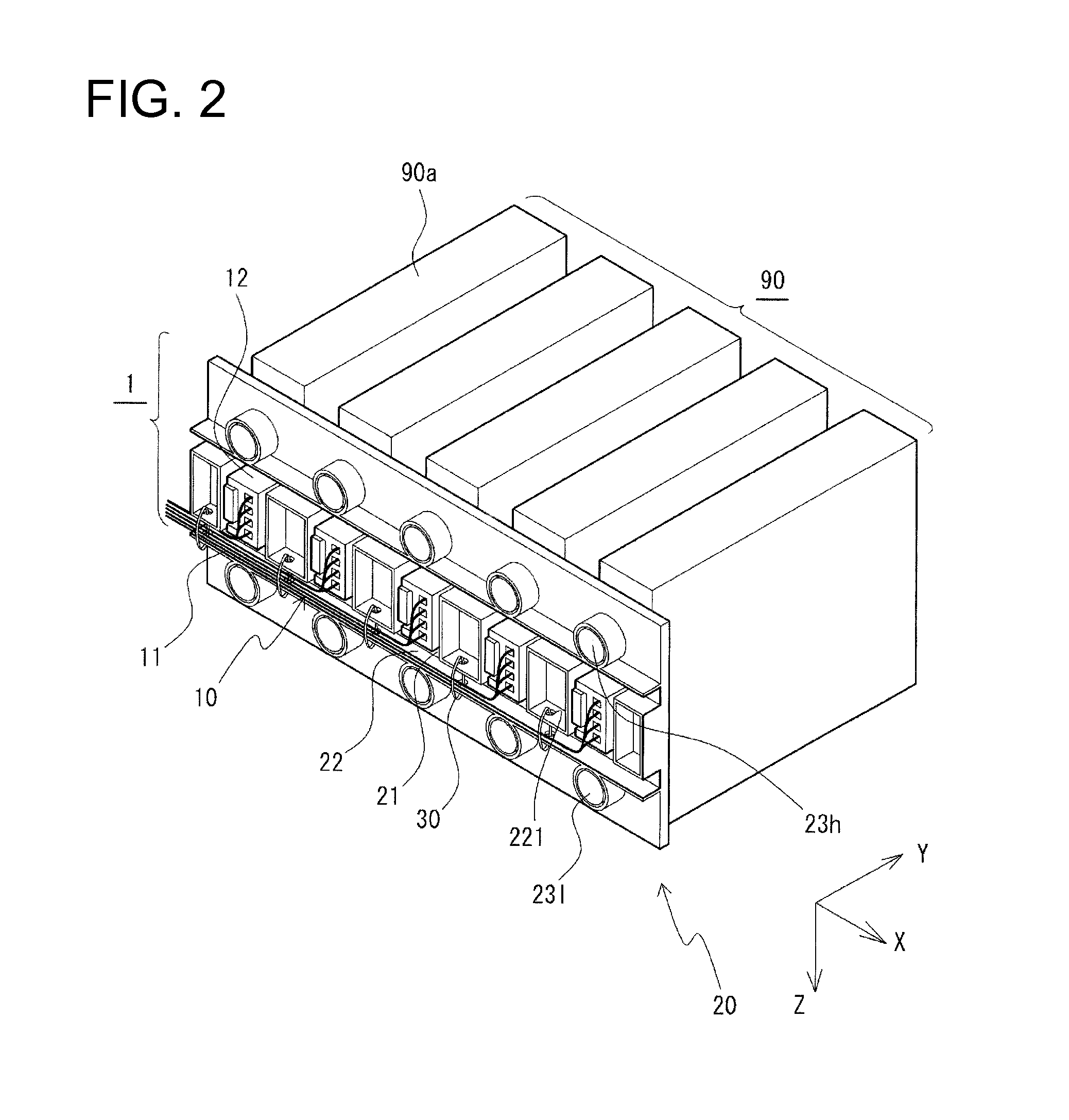
[0022]A wiring module 1 according to an embodiment of the present invention is described in detail with reference to the drawings. Note that, in the following description, unless otherwise particularly noted, a stacking direction means a direction in which units 90a constituting a stacked device 90 are stacked (X direction shown in FIGS. 1 to 3), forward and backward directions mean directions along which a side of the unit 90a constituting the stacked device 90 where a fitting portion 91 is provided is a front side and an opposite side thereof is a rear side (Y directions shown in FIGS. 1 to 3), and a height (vertical) direction means a direction perpendicular to the stacking direction and forward and backward directions (Z direction shown in FIGS. 1 to 3).

[0023]First, the stacked device 90 for which the wiring module 1 according to the embodiment of the present invention is preferably used is briefly described. The stacked device 90 is a device formed by stacking a plurality of id...


PUM


Abstract

A wiring module (1) includes a wiring harness (10) including a plurality of wires (11) and connectors (12) fixed to ends of the respective wires (11) and fittable into fitting portions (91) of a stacked device (90). A positioning member (20) is fixed to the wiring harness (10) and capable of being positioned at a predetermined position with respect to the stacked device (90). The positioning member (20) includes connector fixing portions (21) arranged at the same intervals as the fitting portions (91) of the stacked device (90). The connector fixing portion (21) positions each connector (12) of the wiring harness (10) fixedly at a position facing the corresponding fitting portion (91) when the positioning member (20) is positioned at the predetermined position with respect to the stacked device (90).

Description

BACKGROUND[0001]1. Field of the Invention[0002]This invention relates to a wiring model for wiring a stacked device formed by stacking a plurality of units.[0003]2. Description of the Related Art[0004]Japanese Unexamined Patent Publication No. 2005-151677 discloses a power supply device in which a plurality of power supply units are stacked (arranged). Without being limited to such a power supply device, there are many devices formed by stacking identically or similarly configured units (hereinafter, such devices are called stacked devices).[0005]In electrically connecting a stacked device to another device, a wiring harness including a plurality of wires corresponding to the number of units constituting the stacked device is used in many cases. Connectors are provided on ends of the respective wires of the wiring harness. Predetermined corresponding connectors have to be connected to connector fitting portions of the respective units constituting the stacked device.[0006]However, s...

Claims


Application Information

Patent Timeline
IPC IPC(8): H05K7/06
CPCH05K7/06H01R13/518H05K7/1439H01R9/2416H01R13/631H01R13/642H05K7/1435H05K7/1477
Inventor OKAMOTO, RYOYAHIRAMITSU, HIROOMIHIRAI, HIROKIKASUGAI, MASAKUNI
Owner AUTONETWORKS TECH LTD
Why Eureka
Try Eureka