Connector

a connector and connector technology, applied in the field of connectors, can solve the problems of reducing the difficulty of the above-described connector to satisfy both, and achieve the effects of improving the shielding characteristics of the connector, facilitating the electrical connection, and improving the strength of the body

Inactive Publication Date: 2009-12-29
HOSIDEN CORP
View PDF4 Cites 17 Cited by
  • Summary
  • Abstract
  • Description
  • Claims
  • Application Information

AI Technical Summary

Benefits of technology

[0010]By thus embedding at least one of the first and second shield portions partly or entirely in the body, the strength of the body can be improved. Moreover, since both thicknesswise end portions of the body are shielded by the first and second shield portions, suitable shield characteristics can be obtained. When embedding at least one of the first and second shield portions partly or entirely in the body, it is possible to adjust the distance between portions of the first and second shield portions that are embedded in the body and the contacts, making it possible to control impedances.
[0022]In addition, upon embedding part or all of at least one of the first and second shield portions in the body, the distance between the embedded portion and the contacts can be adjusted, making it possible to control impedances. Accordingly, the transmission characteristics of the connector can be improved, and as a result, the connector can be used for high-speed digital signal transmission.

Problems solved by technology

However, if the body is simply slimmed down, the strength of the body decreases.
That is, it is very difficult for the above-described connector to satisfy both of suitable shield characteristics as EMI measures and the slim body.

Method used


Image

  • Connector
  • Connector
  • Connector

Examples


Embodiment Construction

[0031]A connector according to an embodiment of the present invention will be described below with reference to the drawings.

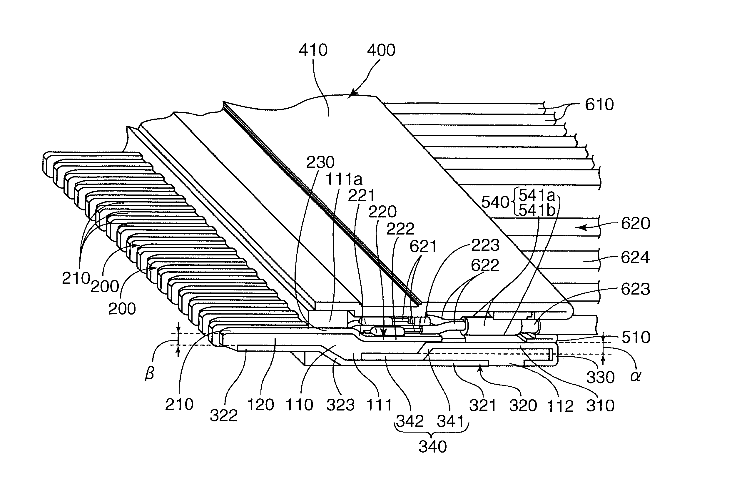
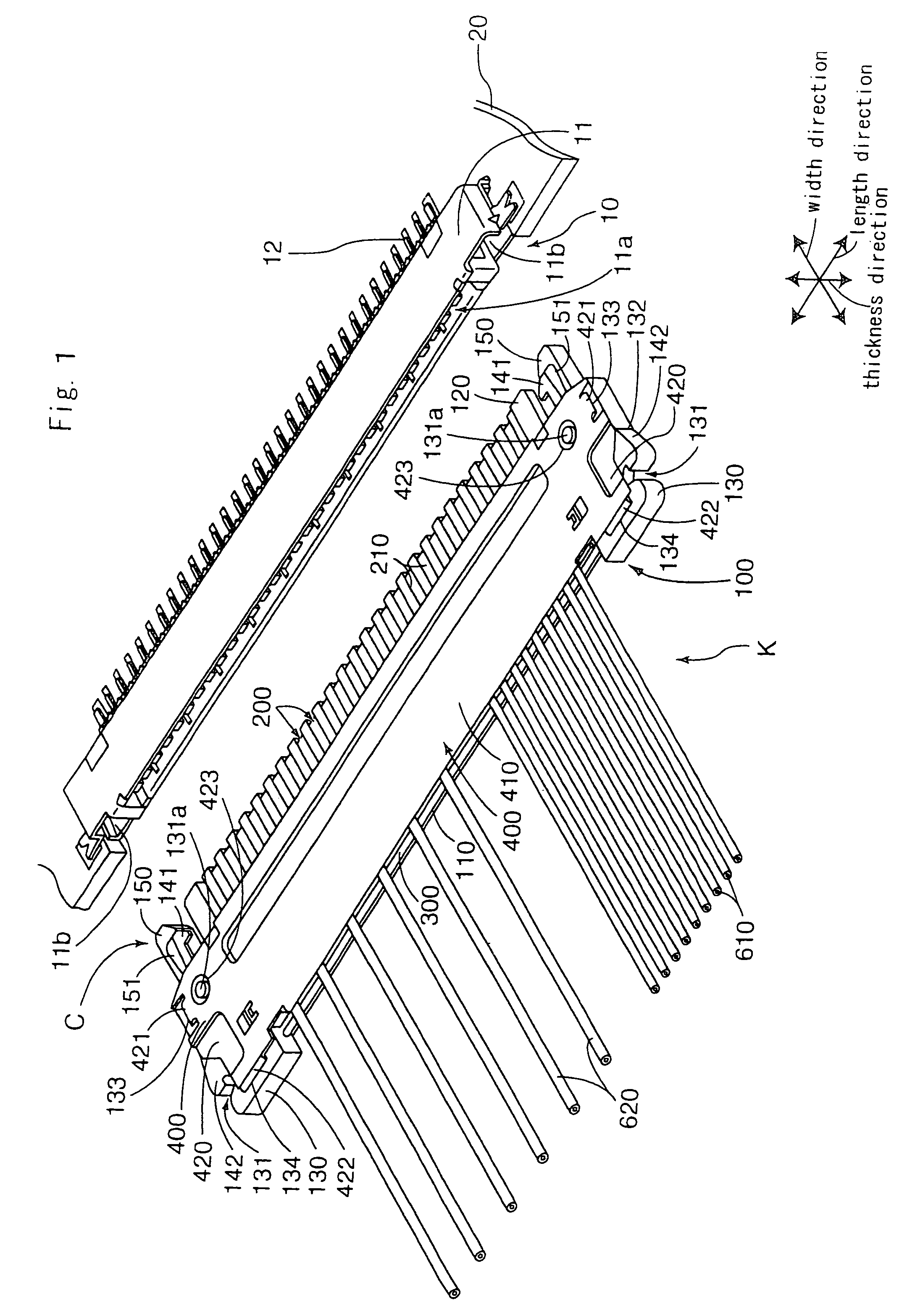
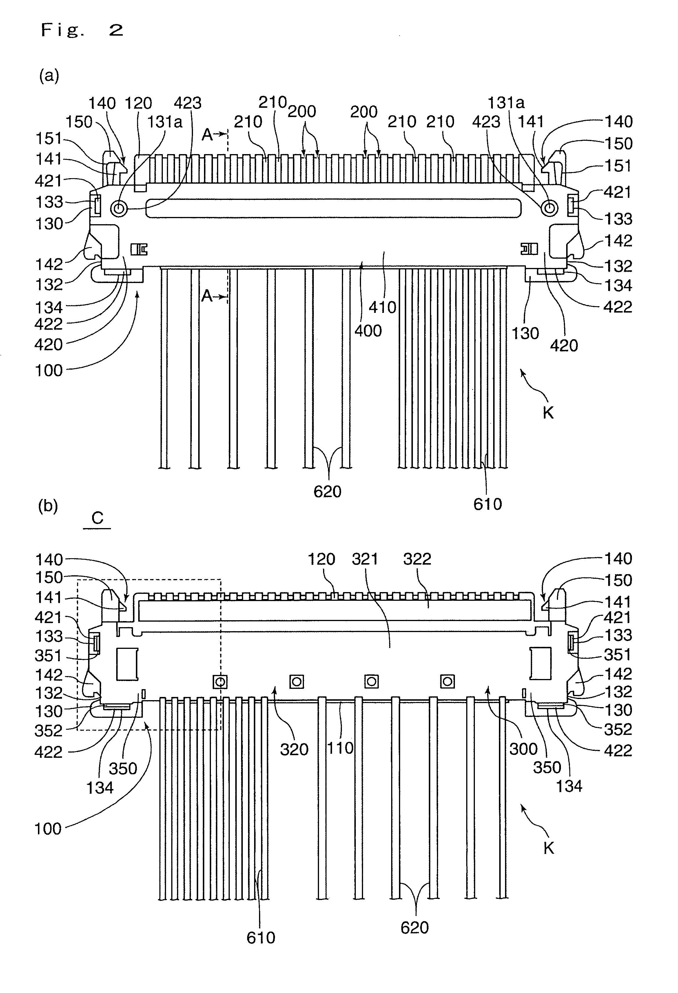
[0032]A connector C shown in FIGS. 1, 2A and 2B is a plug connector which is connectable to a receptacle connector 10. The connector C includes an elongated body 100; a plurality of contacts 200 arranged in a spaced relation along a length of the body 100; a cable assembly K to be connected to the contacts 200; a shield member 300 for shielding the body 100; and a shield cover 400 to be attached to a top face (i.e., first thicknesswise end face) of the body 100. A detailed description will be made below.

[0033]As shown in FIG. 1, the receptacle connector 10 has a elongated main body portion 11 having an opening portion 11a and provided on a circuit board 20 of an electronic device which is not shown; a plurality of contacts 12 arranged on the main body portion 11 in a length direction thereof with a predetermined space provided therebetween; and a ground portio...


PUM


Abstract

A connector includes an elongated body having a plurality of contacts arranged in spaced relation along a length thereof and a shield member for shielding the body. The shield member includes a first shield portion for shielding first thicknesswise end of the body and a second shield portion for shielding a second thicknesswise end of the body. At least one of the first and second shield portions is partly or entirely embedded in the body.

Description

[0001]The present application claims priority under 35 U.S.C. §119 of Japanese Patent Application No. 2007-017,794 filed on Jan. 29, 2007, the disclosure of which is expressly incorporated by reference herein in its entity.BACKGROUND OF THE ART[0002]1. Field of the Invention[0003]The present invention relates to a connector having a plurality of contacts arranged in spaced relation along a length thereof. More particularly, the present invention relates to a plug connector including a plurality of cables connected to the corresponding contacts.[0004]2. Description of the Related Art[0005]For this type of plug connector, there is one that includes an elongated body having a plurality of contacts arranged in spaced relation along a length thereof; a shield cover to be attached to a topside of the body; and a shield member to be attached to an underside of the body and to be electrically connected to the shield cover (see Japanese Patent Application Laid-Open No. 2006-54102).[0006]Such...

Claims


Application Information

Patent Timeline
Patent Type & Authority Patents(United States)
IPC IPC(8): H01R9/03
CPCH01R12/598H01R12/775H01R13/6593H01R13/6589H01R13/65807H01R13/648
Inventor NAGATA, TAKAYUKIKONDO, HAYATO
Owner HOSIDEN CORP
Why Eureka
Try Eureka