
Radar system and method of digital beamforming

a radar system and beamforming technology, applied in the field of radar systems, can solve the problems of high cost of discrete phase shifters, and limited performance of conventional radar systems, and achieve the effect of increasing the reception aperture of the receiving portion of the antenna elements

Active Publication Date: 2009-12-29
APTIV TECH LTD
View PDF31 Cites 74 Cited by
  • Summary
  • Abstract
  • Description
  • Claims
  • Application Information

AI Technical Summary

Problems solved by technology

In such radar systems, a switched beam or mechanically scanned antenna can be incorporated, which can limit performance in one or more ways.
One example of such a conventional radar system generally having limited performance is a mechanically scanned antenna that has an update rate that is too slow to achieve wide angle coverage for a particular application.
Switched beam radar systems can achieve high update rate, but the number of beams is often limited, resulting in either angle coverage that is too narrow or a beamwidth that is too wide for particular applications.
However, electronically scanned antennas typically use discrete phase shifters that are expensive and can introduce excessive radio frequency (RF) loss at particular frequencies, such as 24 GHz and 76 GHz, for example, in automotive radar systems.
In addition to the excessive RF loss at particular frequencies, using discrete phase shifters can be undesirable in an automotive application due to the cost of such a radar system.
Other examples of deficiencies of radar systems used in automobile applications are a limited field of view, an insufficient update rate, inaccuracy, lack of multi-target discrimination, lack of stopped object capability, and inadequate false alarm rates.

Method used


Image

  • Radar system and method of digital beamforming
  • Radar system and method of digital beamforming
  • Radar system and method of digital beamforming

Examples


Embodiment Construction

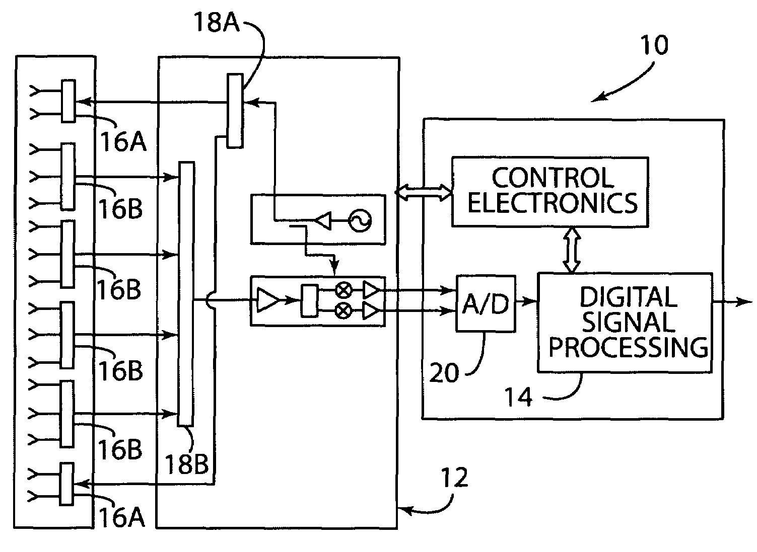
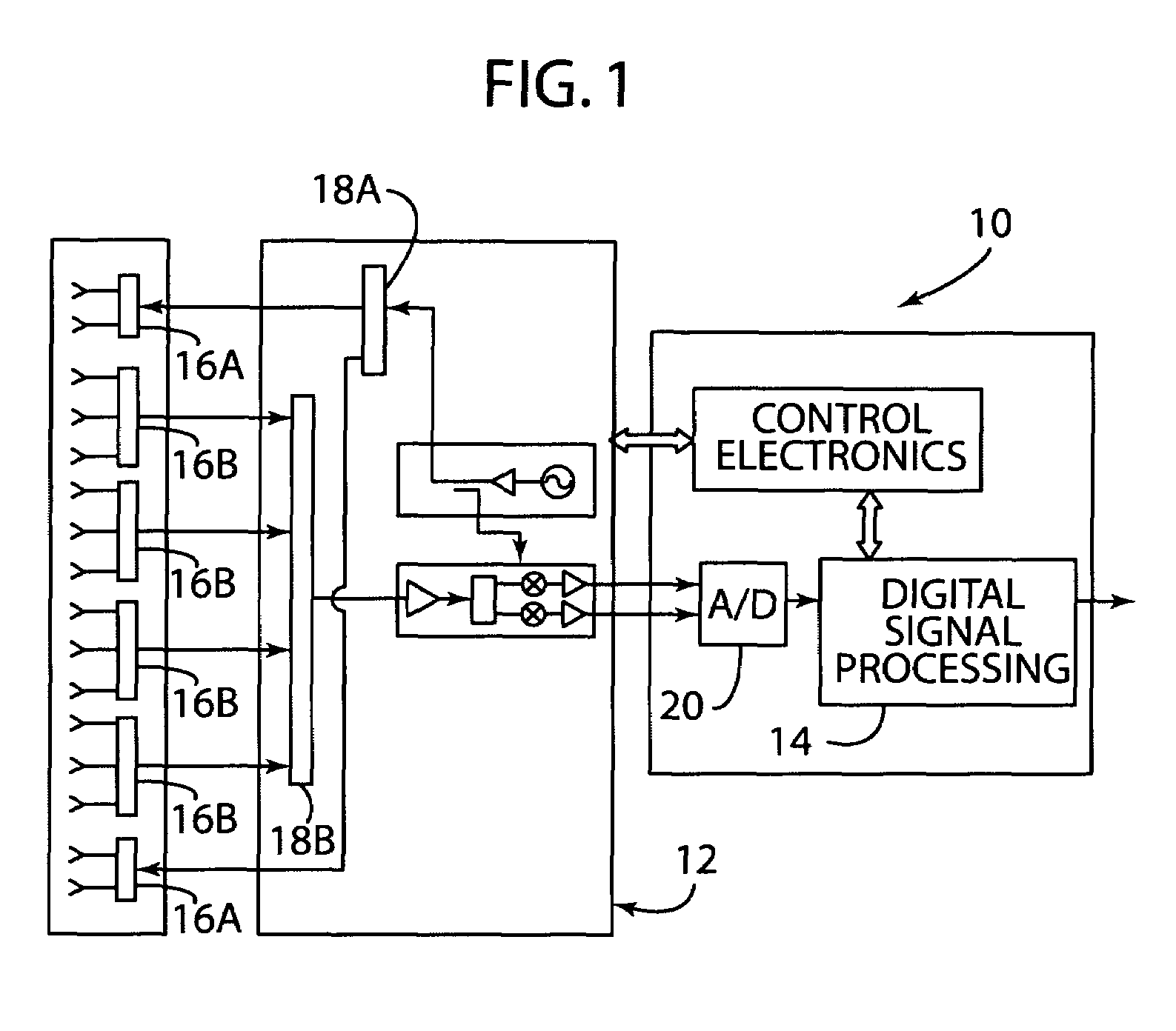
[0018]In reference to FIG. 1, a radar system is generally shown at reference identifier 10. The radar system 10 includes a transceiving device generally indicated at 12, a processor 14, and a plurality of antenna elements 16. Thus, the radar system 10 is an electronically scanned radar system with digital beamforming, according to one embodiment. An exemplary electronically scanned radar system with digital beamforming is disclosed in U.S. Patent Application Publication No. 2007 / 0001897 A1, entitled “DIGITAL BEAMFORMING FOR AN ELECTRONICALLY SCANNED RADAR SYSTEM”, which is hereby incorporated herein by reference.

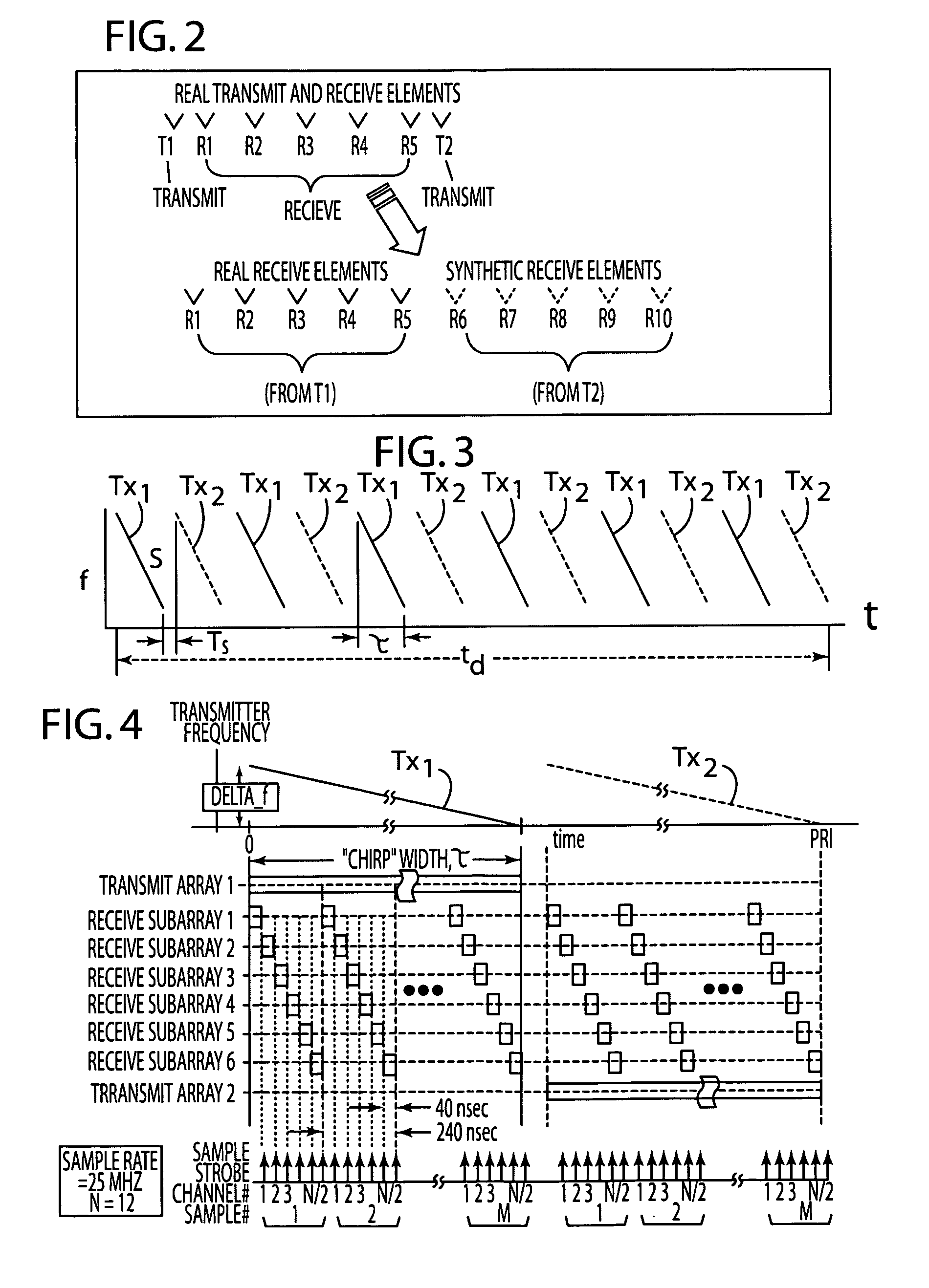
[0019]According to one embodiment, the plurality of antenna elements include a transmitting portion of antenna elements 16A and a receiving portion of antenna elements 16B, such that the receiving portion of antenna elements form a plurality of subarrays that, when the received signals are combined in the processor 14, represent real and synthetic antenna elements. The trans...


PUM


Abstract

A radar system and method is provided, in which the radar system includes a first transmitting portion of antenna elements, a second transmitting portion of antenna elements, and a receiving portion of antenna elements, such that the receiving antenna elements form a plurality of subarrays that represent real and synthetic antenna elements. The radar system further includes a transceiving device having a switching matrix. At least first and second switching transmit antenna elements are configured and time-multiplexed, wherein a receive aperture of the receiving antenna elements is increased. A first signal transmitted is received by the real antenna elements and a second signal transmitted is received by the real antenna elements, and combined so that the signals received from the first switching transmit antenna element represents a signal received by the real receive antenna element, and the signal received from the second switching transmit antenna element represents a signal received by the synthetic receive antenna element.

Description

CROSS-REFERENCE TO RELATED APPLICATION[0001]This application claims the benefit under 35 U.S.C. §119(e) of U.S. Provisional Patent Application No. 60 / 995,549, filed on Sep. 27, 2007, the entire disclosure of which is hereby incorporated herein by reference.TECHNICAL FIELD[0002]The present invention generally relates to a radar system and method of operating thereof, and more particularly, to a radar system including a method of digital beamforming and detecting targets.BACKGROUND OF THE DISCLOSURE[0003]Generally, some known radar systems achieve angle coverage with multiple signal beams, depending upon the application with which the radar system is used. In such radar systems, a switched beam or mechanically scanned antenna can be incorporated, which can limit performance in one or more ways. One example of such a conventional radar system generally having limited performance is a mechanically scanned antenna that has an update rate that is too slow to achieve wide angle coverage fo...

Claims


Application Information

Patent Timeline
Patent Type & Authority Patents(United States)
IPC IPC(8): G01S13/00
CPCG01S7/034G01S13/524H04B7/0842H01Q3/24H04B7/0617H01Q1/28G01S13/26G01S13/343G01S13/582G01S13/931G01S2013/93271G01S7/2883
Inventor ALLAND, STEPHEN W.SEARCY, JAMES F.
Owner APTIV TECH LTD
Learn More