Optical module with adhesively mounted filter

a technology of optical modules and filters, applied in the field of optical modules, can solve the problems of filter falling out of the barrel, non-uniformity and/or insufficiency,

Inactive Publication Date: 2009-12-29
GOLD CHARM LTD
View PDF4 Cites 151 Cited by
  • Summary
  • Abstract
  • Description
  • Claims
  • Application Information

AI Technical Summary

Benefits of technology

[0007]An optical module includes a lens barrel. At least one lens and a spacer are mounted in the lens barrel. A filter is glued (i.e., adhesively mounted) to both the lens barrel and the spacer with an adhesive, so as to prevent the at least one lens and the spacer from falling out of the lens barrel.

Problems solved by technology

However, the non-uniformity and / or the insufficiency (e.g., not enough initially applied; not adequately durable; etc.) of the adhesive will likely allow the filter to fall out of the barrel, in the long run.

Method used


Image

  • Optical module with adhesively mounted filter
  • Optical module with adhesively mounted filter
  • Optical module with adhesively mounted filter

Examples


Embodiment Construction

[0016]Reference will now be made to the drawings to describe in detail at least one preferred embodiment of the present optical module.

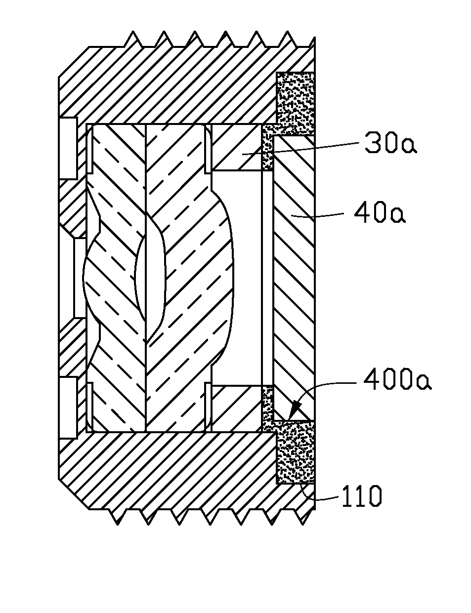
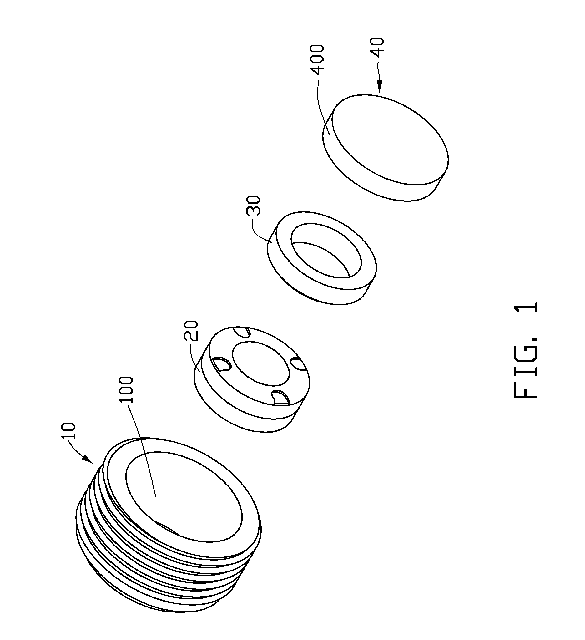
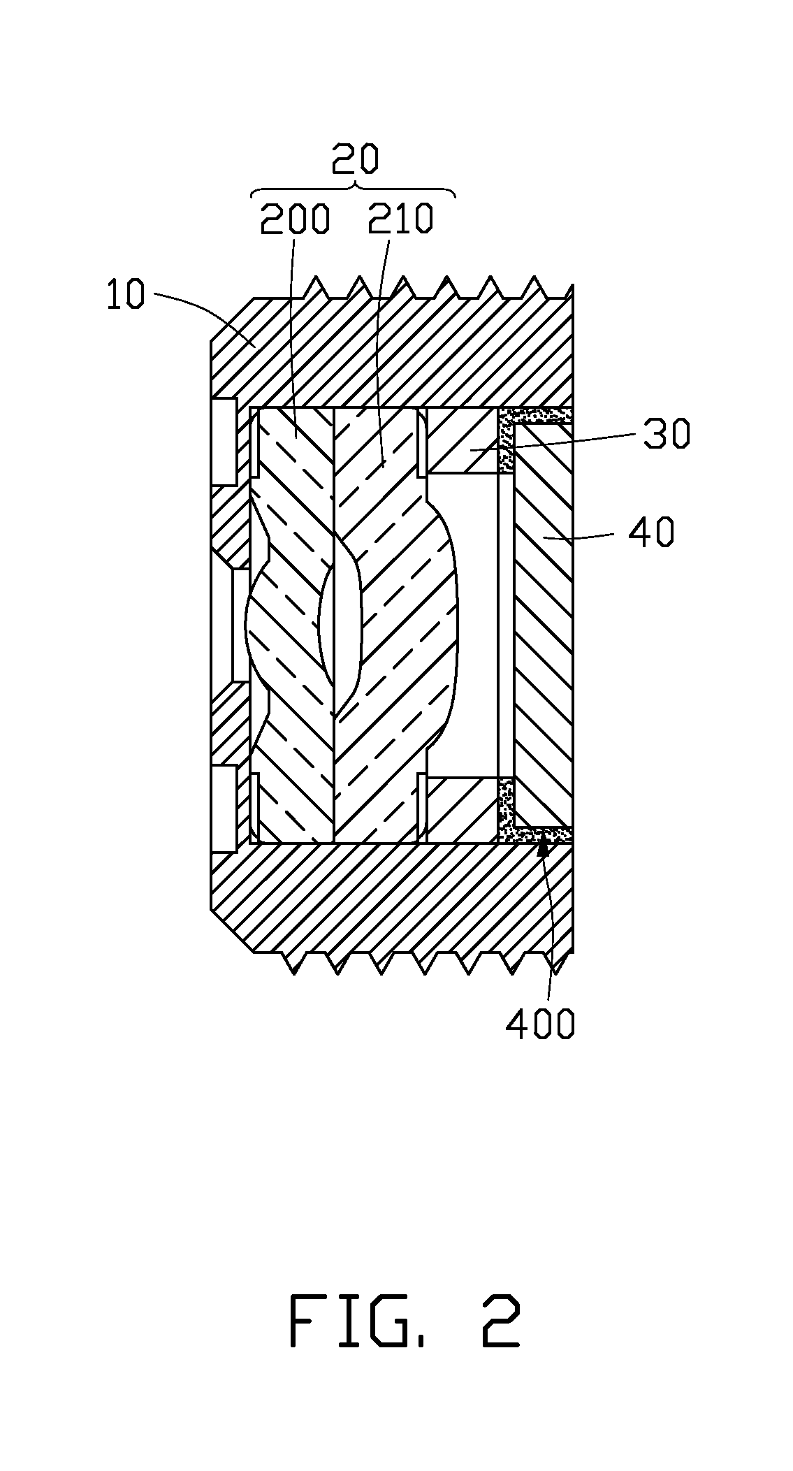
[0017]Referring to FIGS. 1 and 2, an optical module, according to a first present embodiment, includes a lens barrel 10, a lens module 20, a spacer 30, and a filter 40. The lens module 20, the spacer 30, and the filter 40 are engagingly received in the lens barrel 10, one on top of the other, in that order.

[0018]The lens barrel 10 is substantially a hollow cylinder, having a partially-closed end and an open end. The open end is opposite to the partially-closed end. The partially-closed end is adjacent to the lens module 20, and the open end is adjacent to the filter 40. The partially-closed end particularly includes a lip / ledge (not labeled) that extends inwardly of the main portion of the lens barrel 10. The lip / ledge serves to retain the lens module 20 within the lens barrel 10 and also defines a light aperture through which light passing through t...


PUM


Abstract

An optical module includes a lens barrel (10). At least one lens (20) and a spacer (30) are mounted in the lens barrel. A filter (40) is glued to the lens barrel and the spacer with an adhesive so as to prevent the at least one lens and the spacer from falling out of the lens barrel.

Description

BACKGROUND OF THE INVENTION[0001]1. Technical Field[0002]The present invention relates to optical modules used in photography and imaging equipment and, particularly, to optical modules for digital cameras.[0003]2. Description of the Related Art[0004]In recent years, camera modules for taking photos have begun to be incorporated in mobile terminals, such as mobile phones and lap-top computers. Most mobile terminals devices are, progressively becoming more miniaturized over time, and digital camera modules are, correspondingly, becoming smaller and smaller. Nevertheless, in spite of the small size of a contemporary digital camera module, consumers still demand excellence in image quality.[0005]Optical modules used for digital camera modules typically include a barrel, a lens module, a spacer, and a filter. The lens module and the spacer are received in the barrel. Generally, the filter is fixed with a spacer in the barrel, by using an adhesive, for example. However, the non-uniformit...

Claims


Application Information

Patent Timeline
Patent Type & Authority Patents(United States)
IPC IPC(8): G02B7/02
CPCG02B7/025
Inventor CHIANG, TSUNG-WEI
Owner GOLD CHARM LTD
Why Eureka
Try Eureka