Bone-conduction handset

a handset and bone-conduction technology, applied in the field of bone-conduction handsets, can solve the problems of inability to achieve both a satisfactory prevention of howling and a satisfactory prevention of sound leakage, and achieve the effects of preventing howling from occurring, preventing sound leakage, and hard for speaker unit vibration

Inactive Publication Date: 2009-12-29
TEMCO JAPAN
View PDF8 Cites 50 Cited by
  • Summary
  • Abstract
  • Description
  • Claims
  • Application Information

AI Technical Summary

Benefits of technology

[0013]In the bone-conduction type handset of the present invention, the speaker mounting member is disposed perpendicularly to opposite surfaces of the main body of the handset and of the speaker unit, and provided with the connection portion, through which the main body of the handset is isolated from the speaker unit. Consequently, the speaker unit is sufficiently isolated from the main body of the handset so that it is hard for vibrations of the speaker unit from transferring to the main body of the handset. Due to this, when a large output is issued from the speaker unit, it is possible for the handset of the present invention to prevent howling from occurring and also prevent leakage of a sound.
[0014]In the invention as set forth in claim 4, the speaker unit is swingable in operation, which makes it possible for a user of the handset to change an angle of the speaker unit relative to an abutting surface of the user's side head portion. Due to this, it is possible to improve the handset of the present invention in fittability in use.

Problems solved by technology

However, since the resilient board is brought into area contact with both the speaker unit and the main body of the handset, it is impossible to have the speaker unit sufficiently isolated from the main body of the handset.
Due to this, when a large output is issued from the speaker, it is impossible to achieve both a satisfactory prevention of howling and a satisfactory prevention of leakage of a sound.
These are problems inherent in the conventional method.

Method used


Image

  • Bone-conduction handset
  • Bone-conduction handset
  • Bone-conduction handset

Examples


Embodiment Construction

[0015]Next, with reference to the accompanying drawings, preferred embodiments for carrying out the present invention will be described.

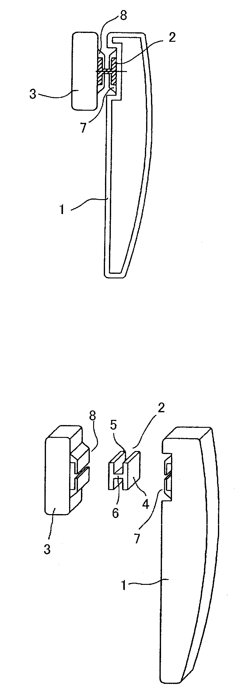
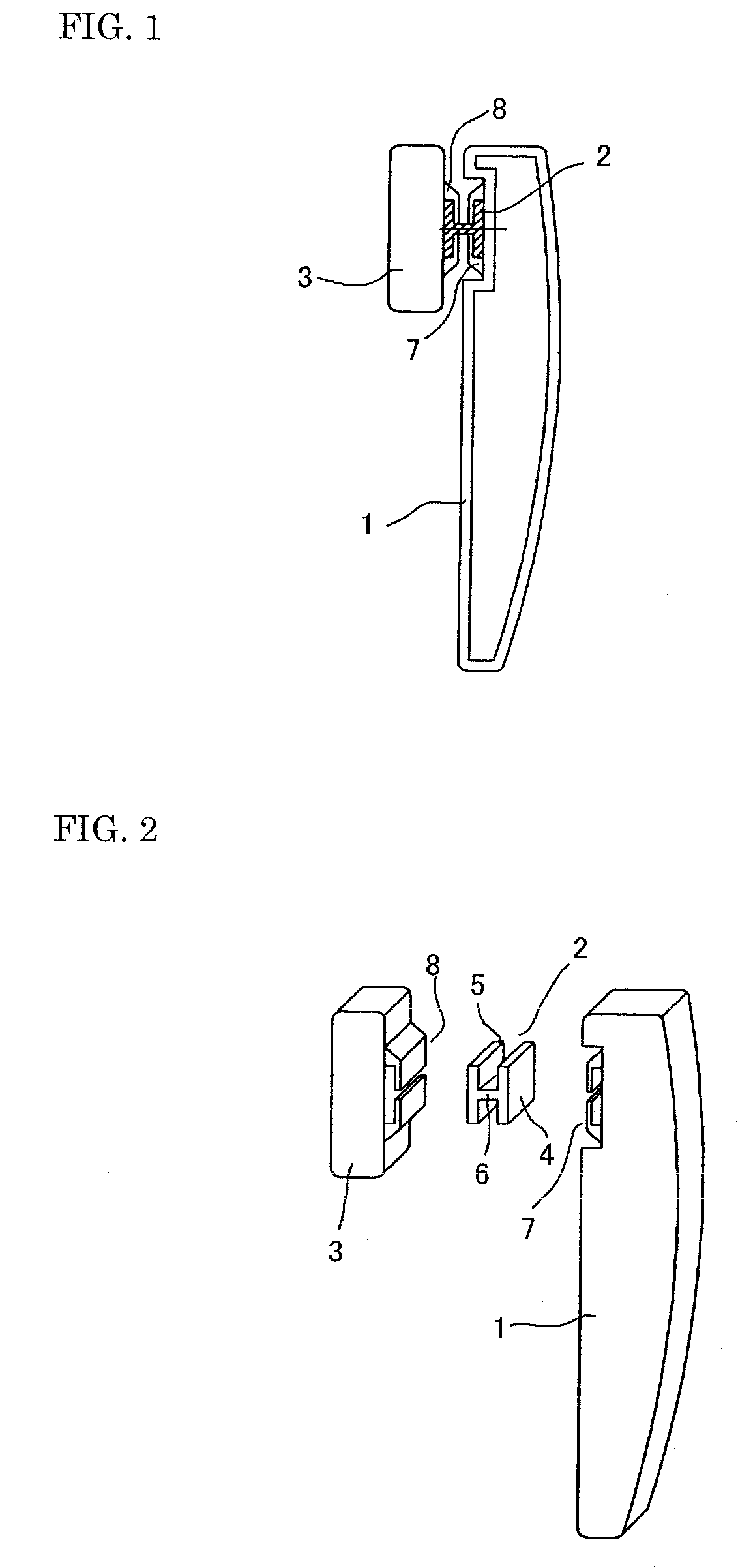
[0016]FIG. 1 is a side view illustrating a bone-conduction handset of the present invention in construction (wherein an internal mechanism of the handset is not shown). FIG. 2 is an exploded perspective view of the handset. The bone-conduction handset is constructed of: a main body 1 of the handset; and, a bone-conduction speaker, which is mounted in the main body 1 of the handset through a speaker mounting member 2. Although not shown in the drawings, appropriate instruments and cables necessary for the handset are incorporated in the main body 1 of the handset.

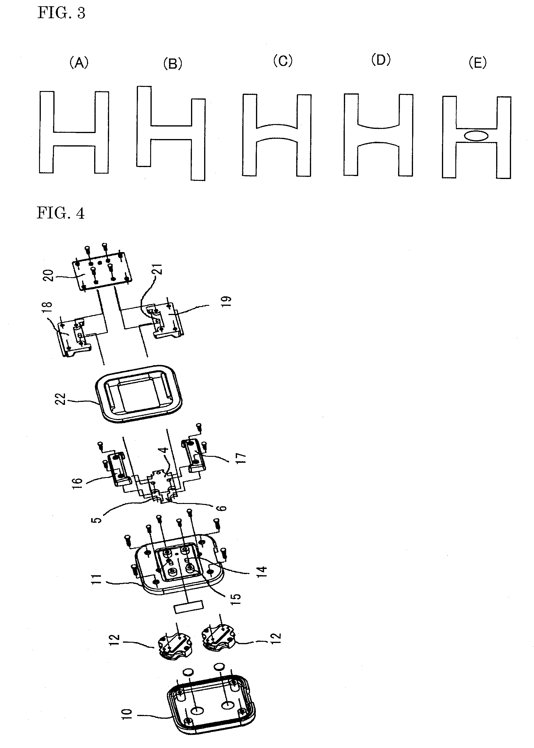
[0017]The speaker mounting member 2 shown in FIGS. 1 and 2 assumes an H-shaped form in cross-section. This mounting member 2 is constructed of: an engaging plate 4 in the side of the main body, which plate 4 is engaged with an inner surface of the main body 1 of the handset; an engaging plat...


PUM


Abstract

The object is to provide a bone-conduction handset, which has its main body (1) sufficiently isolated from a bone-conduction speaker unit (3) so that: the chances that howling and sound leaking may occur are reduced; and, the handset is improved in easiness in use. In the handset, the speaker unit (3) is mounted on the main body (1) through a speaker mounting member (2) made of a vibration-proof material. The mounting member (2) is characterized by comprising a connection portion (6), which is disposed perpendicularly to both the handset body (1) and the speaker unit (3) in a manner such that the main body (1) and the speaker unit (3) have their opposed inner surfaces disposed adjacent to opposite sides of the connection portion (6), whereby the main body (1) is isolated from the speaker unit (3).

Description

TECHNICAL FIELD[0001]The present invention relates to a bone-conduction handset, and more particularly to a bone-conduction handset necessary for a telephone set, which uses a bone-conduction speaker as a speaker thereof.BACKGROUND ART[0002]A bone-conduction speaker transmits an audio signal through a skull's vibration, not through air vibrations. Consequently, the bone-conduction speaker is substantially free from an external environmental noise. Due to this, the bone-conduction speaker is well adapted to any person who has difficulty in hearing, and therefore coming into increasingly wide spread use in communication instruments.[0003]Such a bone-conduction speaker is used in an ordinary telephone set in a condition in which the bone-conduction speaker is fixedly mounted on an end portion of a main body 1 of the handset of the telephone set through a resilient board made of plastics, rubber or like materials good in damping properties in order to prevent howling from occurring, whe...

Claims


Application Information

Patent Timeline
Patent Type & Authority Patents(United States)
IPC IPC(8): H04R25/00H04M1/03H04R1/00
CPCH04M1/03H04R2499/11H04R2460/13H04R1/00H04R1/02
Inventor FUKUDA, MIKIO
Owner TEMCO JAPAN
Why Eureka
Try Eureka