Dispersion and aeration apparatus for compressed air foam systems

a foam system and aeration apparatus technology, applied in lighting and heating apparatus, combustion process, mixers, etc., can solve the problems of limiting the degree to which foam can be expanded, the foam may have time to collapse, and the foam cannot expand to the extent that it can

Inactive Publication Date: 2010-01-05
RICHARDS WILLIAM HENRY
View PDF5 Cites 4 Cited by
  • Summary
  • Abstract
  • Description
  • Claims
  • Application Information

AI Technical Summary

Benefits of technology

[0007]The present invention is directed to a dispersion and aeration apparatus which may at least partially overcome at least one of the abovementioned disadvantages or provide the consumer with a useful or commercial choice.

Problems solved by technology

Nozzles of this type, due mainly to the use of the injected pressurised gas to both convey and expand the foam, suffer from a limited degree to which the foam can be expanded.
In addition to this, the foam may have time to collapse between injection of the pressurised gas and dispersion from the nozzle.
This device has a disadvantage in that the amount of air which is drawn into the nozzle is directly proportional to the flow rate of the foam through the nozzle.
This limits the degree to which the foam can be expanded.

Method used


Image

  • Dispersion and aeration apparatus for compressed air foam systems
  • Dispersion and aeration apparatus for compressed air foam systems
  • Dispersion and aeration apparatus for compressed air foam systems

Examples


Embodiment Construction

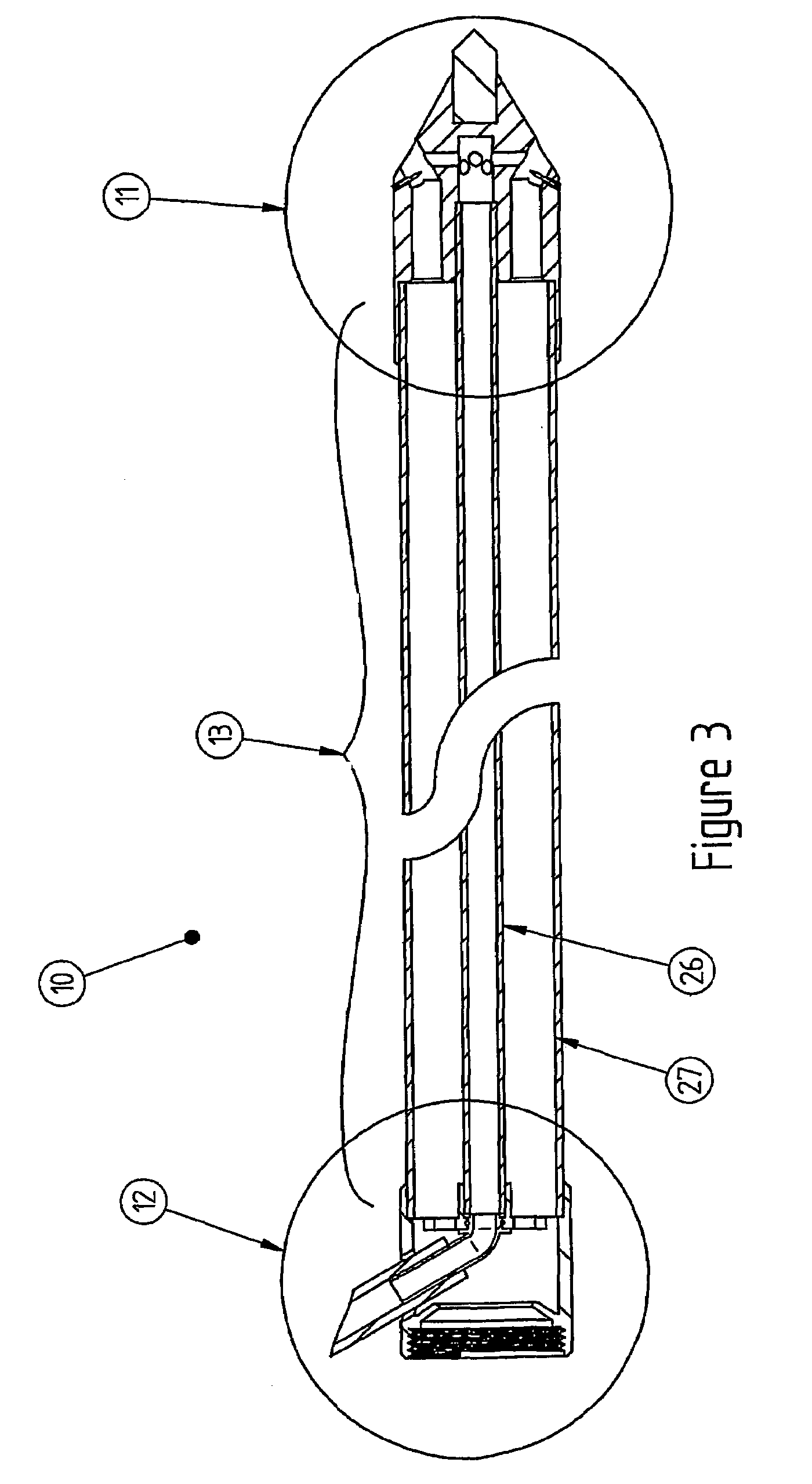
[0062]According to a preferred embodiment of the invention, a dispersion and aeration lance 10 is provided.

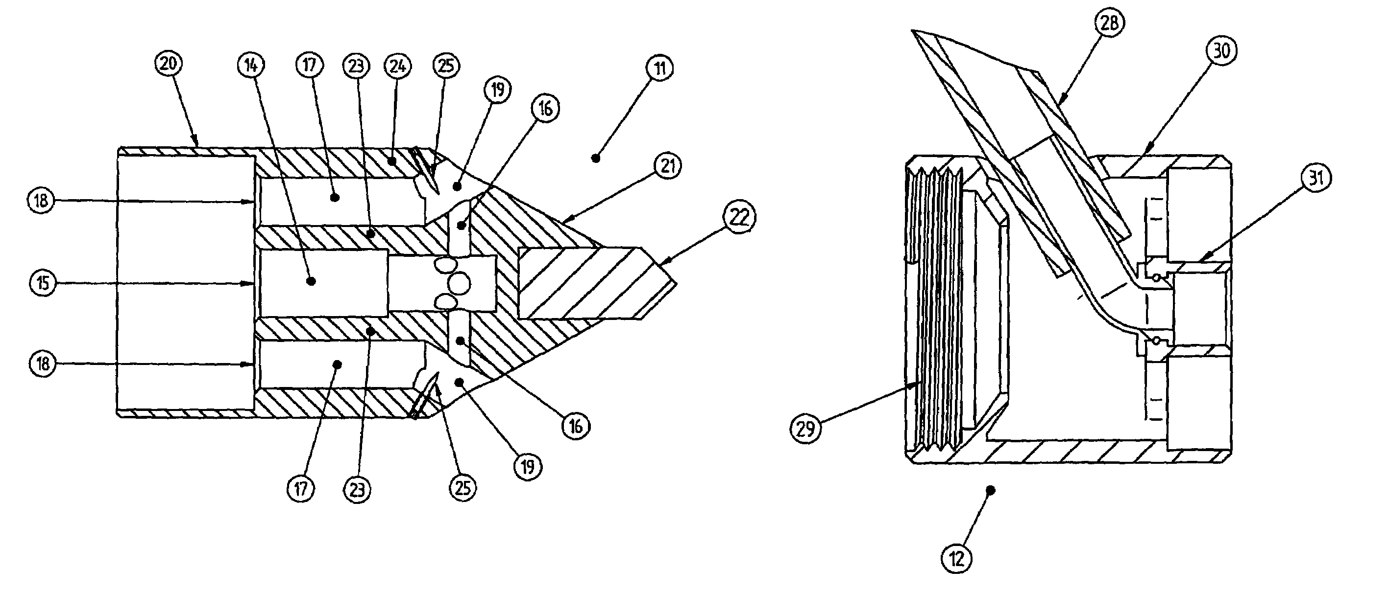
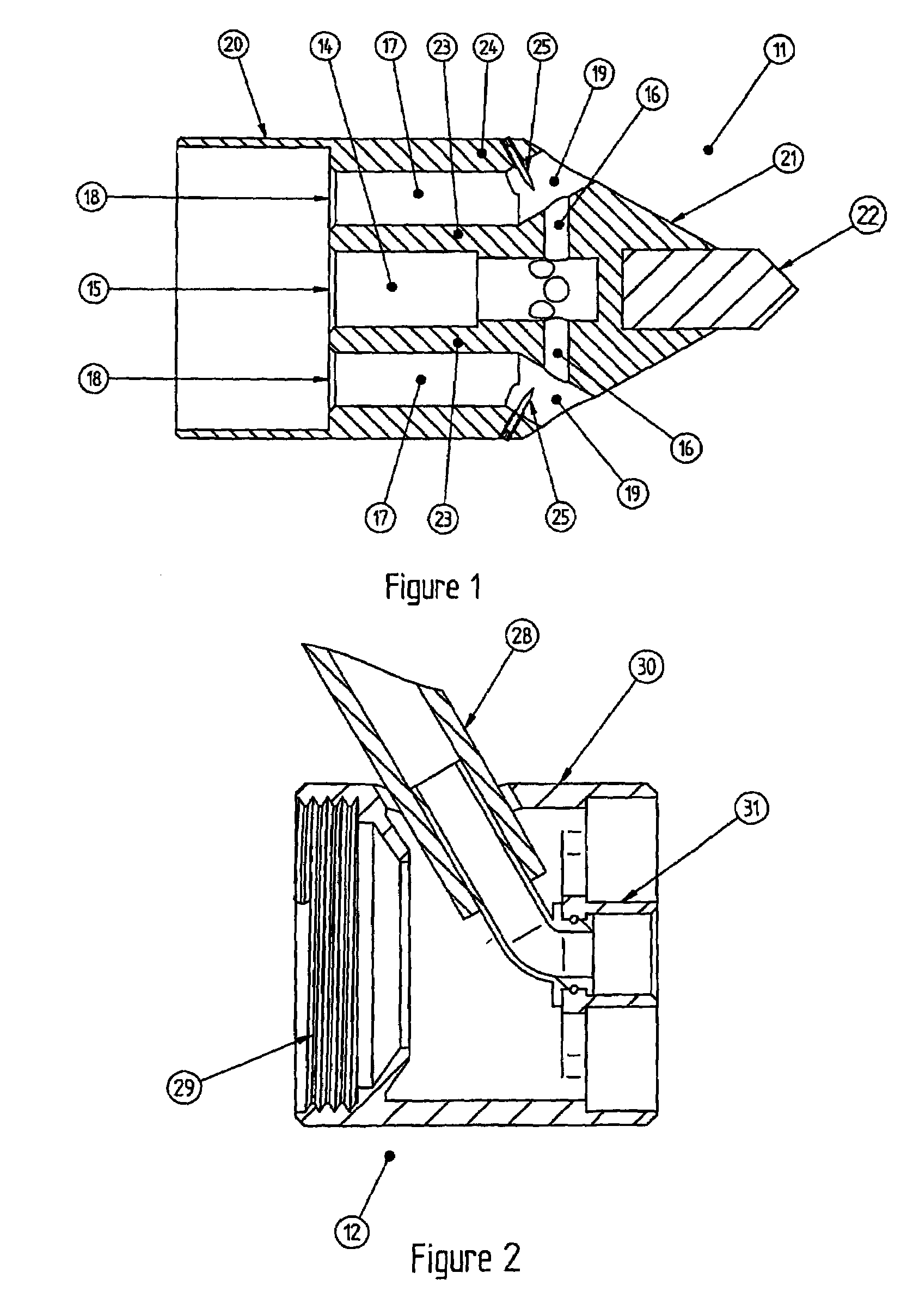
[0063]The dispersion lance as illustrated in FIG. 3 has a nozzle portion 11 (best illustrated in FIG. 1) and a fluid connection portion 12 (best illustrated in FIG. 2) separated by one or more body portions 13. The dispersion lance is attachable directly to a foam hose to supply the foam. A second hose can then be connected to supply the compressed gas to the dispersion lance. The use of the lance allows the placement of the foam inside the building without the need to enter the building.

[0064]A first preferred embodiment of the nozzle portion 11 as illustrated in FIG. 1 has a compressed gas passage 14 with an inlet 15 and multiple outlets 16 generally for compressed air and a foam passage 17 having an inlet 18 and multiple outlets 19.

[0065]Each gas outlet 16 is located such that the gas exiting said gas outlet 16 mixes with the foam as it exits a foam outlet 19 to further aera...


PUM

PropertyMeasurementUnit
angleaaaaaaaaaa
angleaaaaaaaaaa
angleaaaaaaaaaa

Abstract

A dispersion and aeration apparatus including a nozzle portion (11) having a first passage (14) having at least one inlet (15) and at least one outlet (16) for a first fluid, and a second passage (17) having at least one inlet (18) and at least one outlet (19) for a second material, the first passage outlets (16) located so that the first fluid mixes with the second material as it exits the second passage outlet (19) to aerate and disperse the second material in a predetermined direction.

Description

FIELD OF THE INVENTION[0001]The present invention relates to dispersion apparatus and in particular to apparatus for the dispersion of fluids, particularly liquids, rapidly and in multiple directions.BACKGROUND ART[0002]Compressed air foam (CAF) was developed in the 1970s in Texas as an innovative approach for fighting grassland fires in areas where water is extremely scarce. The system combines two technologies, an agent to reduce the surface tension of water and compressed air to produce an expanded volume of fire extinguishing agent. The surface tension reduction, which makes water much more efficient as an extinguishing agent, is accomplished by introducing a small percentage of Class A foam concentrate into the water stream. Compressed air is then injected into the solution to expand the foam, creating a mass of foam bubbles to provide a much greater volume of extinguishing agent in a form that has the ability to stick to vertical surfaces and flow over horizontal surfaces, for...

Claims


Application Information

Patent Timeline
Patent Type & Authority Patents(United States)
IPC IPC(8): B05B7/12B05B7/30F23D11/46F23D14/60
CPCA62C5/02A62C31/02A62C31/07A62C31/12B01F3/04446B01F5/045B05B7/0025A62C99/0036B05B7/0043B01F23/235B01F25/313B05B1/02
Inventor RICHARDS, WILLIAM HENRY
Owner RICHARDS WILLIAM HENRY
Why Eureka
Try Eureka