
Sheet feeding apparatus and image forming apparatus

a technology of feeding apparatus and feeding plate, which is applied in the direction of electrographic process, instruments, transportation and packaging, etc., can solve the problems of inability to stably separate and feed sheets, inability to prevent the rotation of the reverse direction of the retard roller, and the inability to prevent the rotation of the retard roller in the reverse direction

Inactive Publication Date: 2010-01-05
CANON KK
View PDF16 Cites 22 Cited by
  • Summary
  • Abstract
  • Description
  • Claims
  • Application Information

AI Technical Summary

Benefits of technology

The invention is a sheet feeding apparatus that separates and feeds sheets of paper smoothly. It includes a separating roller and a feed roller that work together to separate sheets one by one. A charge eliminating mechanism is also included to remove any electrical charges from the separating roller. This results in a more stable and reliable sheet feeding process.

Problems solved by technology

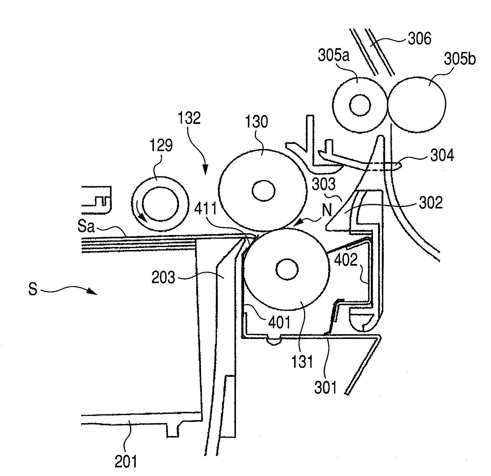
Further, if the sheet S is curled toward the retard roller 131 side, the defective feeding of the bent front edge is more liable to occur.
Thus, the sheets cannot be stably separated and fed.
However, the rotation in the reverse direction of the retard roller 131 cannot be prevented.
Therefore, even if the sheet guide 135 has been arranged, there is a large risk that the front edge of the sheet is come into contact with the retard roller 131 which is reversely rotated and the foregoing problem occurs.

Method used


Image

  • Sheet feeding apparatus and image forming apparatus
  • Sheet feeding apparatus and image forming apparatus
  • Sheet feeding apparatus and image forming apparatus

Examples


Embodiment Construction

[0043]An exemplary embodiment for embodying the invention will be described in detail hereinbelow with reference to the drawings.

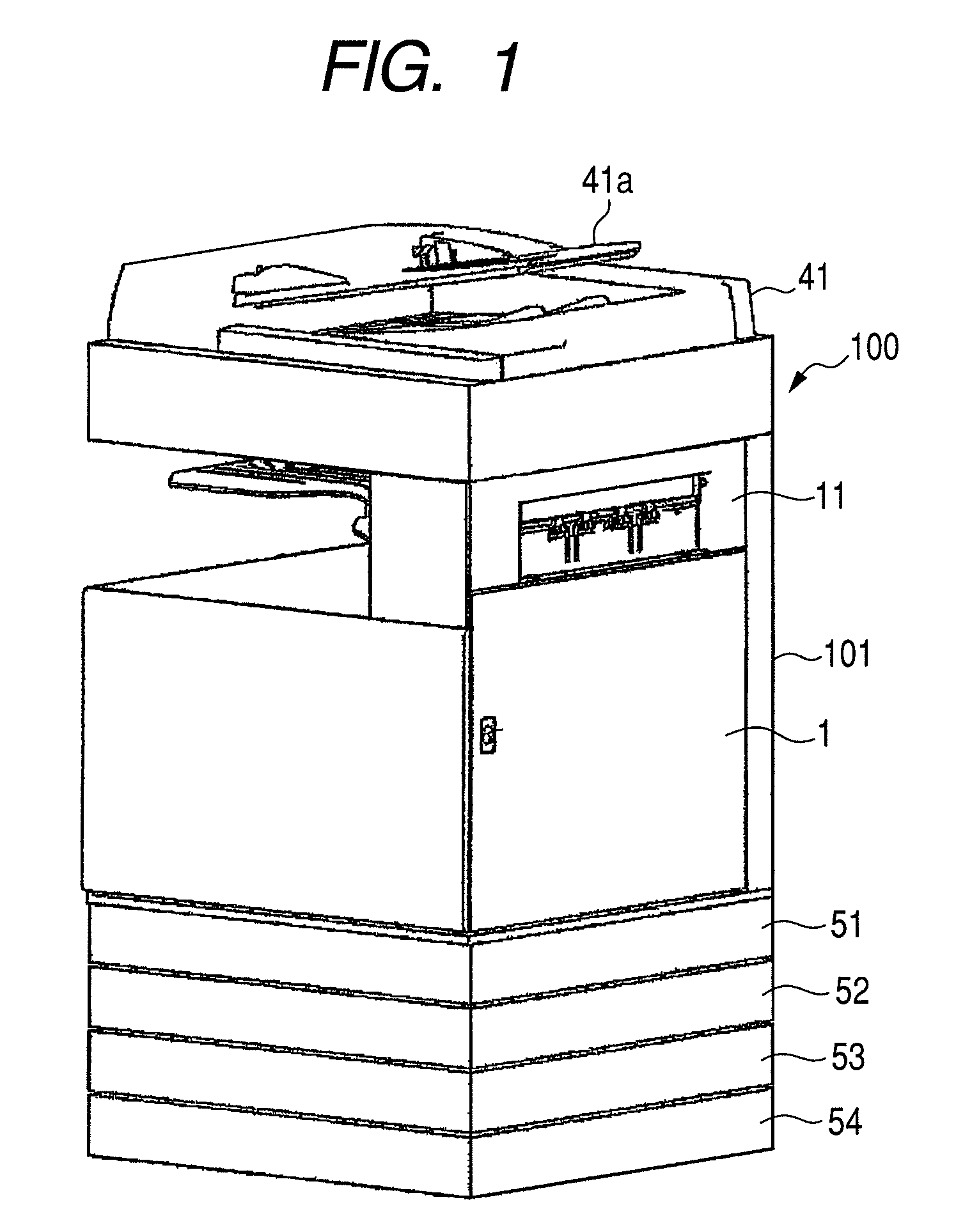
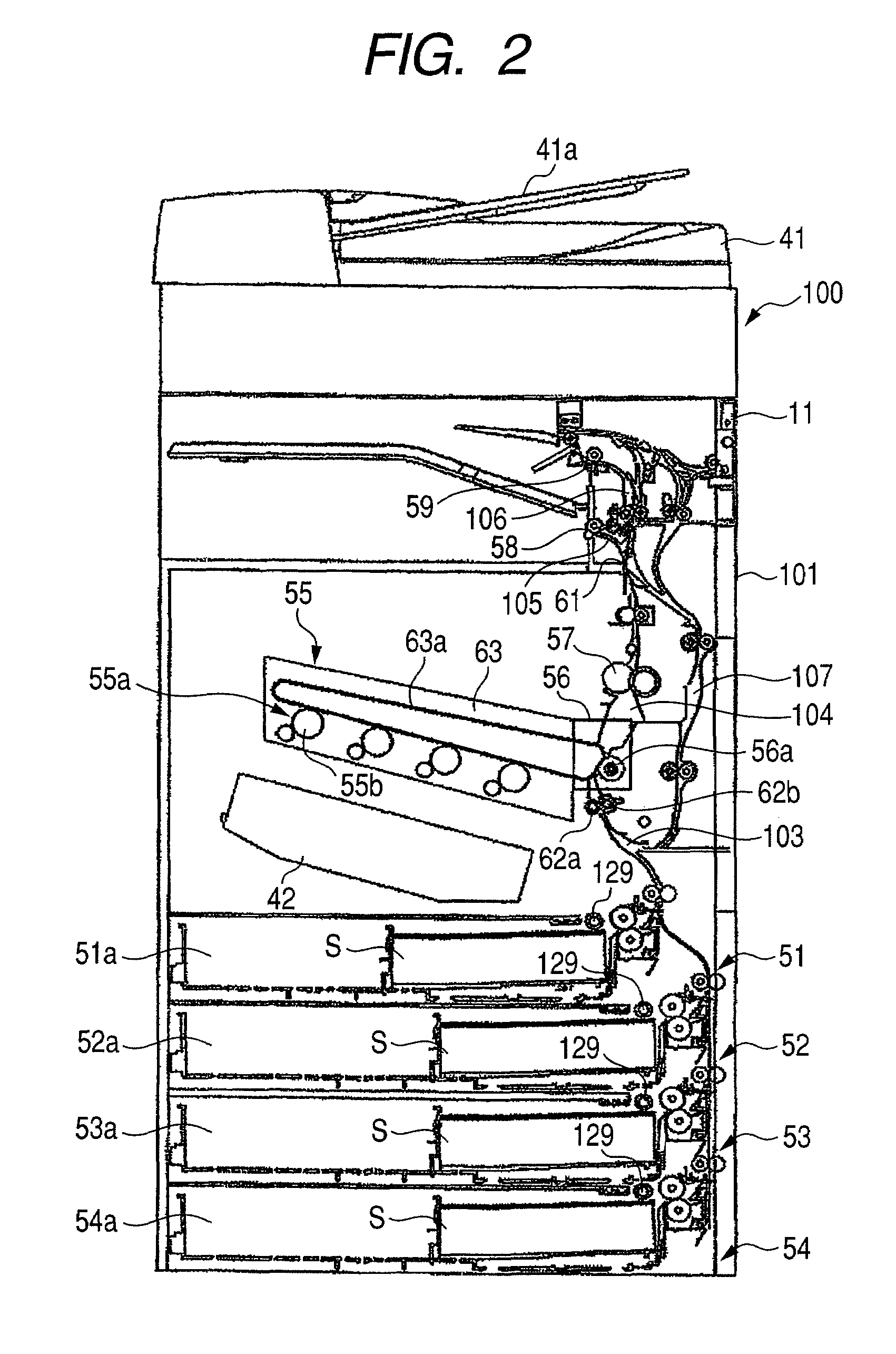
[0044]FIG. 1 is a perspective view of a printer 100 as an example of an image forming apparatus having a sheet feeding apparatus according to the embodiment of the invention. FIG. 2 is a diagram illustrating a schematic construction of the printer.

[0045]In FIG. 1, an image reading unit 41 having an image sensor and the like is provided over a printer main body 101. The image reading unit 41 irradiates light to an original document put on platen glass serving as an original setting base plate and converts reflected light into a digital signal. An automatic document feeder (ADF) 41a conveys the original onto the platen glass in order to read an image of the original.

[0046]As illustrated in FIG. 2, an image forming unit 55 and sheet feeding apparatuses 51 to 54 each for feeding the sheets S to the image forming unit 55 are provided under the image reading uni...


PUM

PropertyMeasurementUnit
flexibleaaaaaaaaaa
bending angleaaaaaaaaaa
conductiveaaaaaaaaaa

Abstract

Sheets fed out of a cassette supporting the sheets by a pickup roller are separated and fed by a sheet separation feeding unit having a feed roller and a separating roller which is rotatable in a direction opposite to a sheet feeding direction. A charge eliminating mechanism for eliminating charges of the separating roller is arranged on the upstream side in the sheet feeding direction in a separation nip portion between the feed roller and the separating roller.

Description

BACKGROUND OF THE INVENTION[0001]1. Field of the Invention[0002]The present invention relates to a sheet feeding apparatus and an image forming apparatus and, more particularly, to a construction of a separation feeding unit for separating and feeding sheets one by one to an image forming unit.[0003]2. Description of the Related Art[0004]Hitherto, an image forming apparatus such as copying apparatus, printer, or facsimile has a sheet feeding apparatus for feeding a sheet to an image forming unit, and the sheet feeding apparatus has a sheet separation feeding unit for separating and feeding the sheets one by one.[0005]As such a sheet separation feeding unit, there is a sheet separation feeding unit having a feed roller and a retard roller (separating roller) which is come into pressure contact with the feed roller and to which a rotating force in the direction opposite to a sheet feeding direction is applied through a torque limiter. In the sheet separation feeding unit of such a ret...

Claims


Application Information

Patent Timeline
Patent Type & Authority Patents(United States)
IPC IPC(8): B65H3/52
CPCB65H3/06B65H3/5261B65H2301/5321B65H2801/06G03G15/00
Inventor HIURA, HIROSHISUGA, TAKESHIITABASHI, TOSHIFUMISEKIGUCHI, HAJIME
Owner CANON KK
Learn More