Electrical connector having vibration-resisting structure

a technology of electrical connectors and vibration-resisting structures, which is applied in the direction of couplings/cases, coupling device connections, electrical apparatus, etc., can solve the problems of connector terminal fitting damage, and connectors that suffer from electrical continuity failure, so as to prevent the shaking of the connector

Inactive Publication Date: 2010-01-05
YAZAKI CORP
View PDF4 Cites 2 Cited by
  • Summary
  • Abstract
  • Description
  • Claims
  • Application Information

AI Technical Summary

Benefits of technology

[0010]It is therefore an objective of the present invention to solve the above problem and to provide a connector, by which the connector can be prevented from being shaken with a simple structure thereof so that the terminal fitting can be prevented from suffering from failure in electrical continuity.
[0015]With the construction described above, the second connector housing includes the groove part into which the end part of the hood part of the first connector housing enters. Therefore, the end part of the hood part enters the groove part so that the first and second connector housings are fixed to each other stably. Accordingly, the connector can be prevented from being shaken with a simple structure thereof so that the connector can be prevented from suffering from failure in electrical continuity due to abrasion of the terminal fitting.
[0017]With the construction described above, the end part of the hood part comes in stable contact with the inner surface of the groove part, so that the first and second connector housings are further stably fixed to each other. Accordingly, the connector can be further prevented from being shaken with a simple structure thereof so that the connector can be prevented from suffering from failure in electrical continuity due to abrasion of the terminal fitting.
[0019]With the construction described above, the inner surface of the groove part closely comes in contact with the end part of the hood part through the resilient member, so that the resilient member is resiliently deformed so as to absorb the shaking of the connector. Accordingly, the connector can be further prevented from being shaken with a simple structure thereof so that the connector can be prevented from suffering from failure in electrical continuity due to abrasion of the terminal fitting. Moreover, by composing the resilient member with heat resisting resilient material, the effect for preventing the shaking of the connector can be prevented from reducing due to heat deterioration.
[0021]With the construction described above, the engaging part closely comes in contact with the mating engaging part through the resilient member and the resilient member is resiliently deformed so as to absorb the shaking of the connector. Accordingly, the connector can be further prevented from being shaken with a simple structure thereof so that the connector can be prevented from suffering from failure in electrical continuity due to abrasion of the terminal fitting. Moreover, by composing the resilient member with heat resisting resilient material, the effect for preventing the shaking of the connector can be prevented from reducing due to heat deterioration.

Problems solved by technology

In such a case, the connector is shaken due to the vibration causing the connector to suffer from failure in electrical continuity due to abrasion of an electrical contact of the terminal fitting.
Therefore, the outer housing of the male housing may be shaken due to vibration, causing the connector to suffer from failure in electrical continuity due to abrasion of an electrical contact of the terminal fitting.
When things come to the worst, the terminal fitting may be damaged.

Method used


Image

  • Electrical connector having vibration-resisting structure
  • Electrical connector having vibration-resisting structure
  • Electrical connector having vibration-resisting structure

Examples


Embodiment Construction

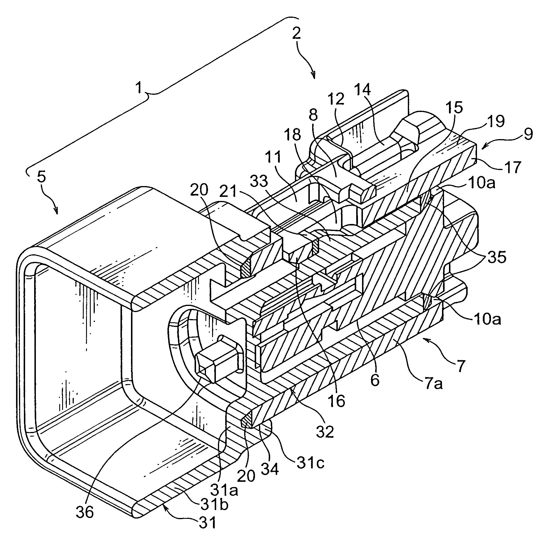
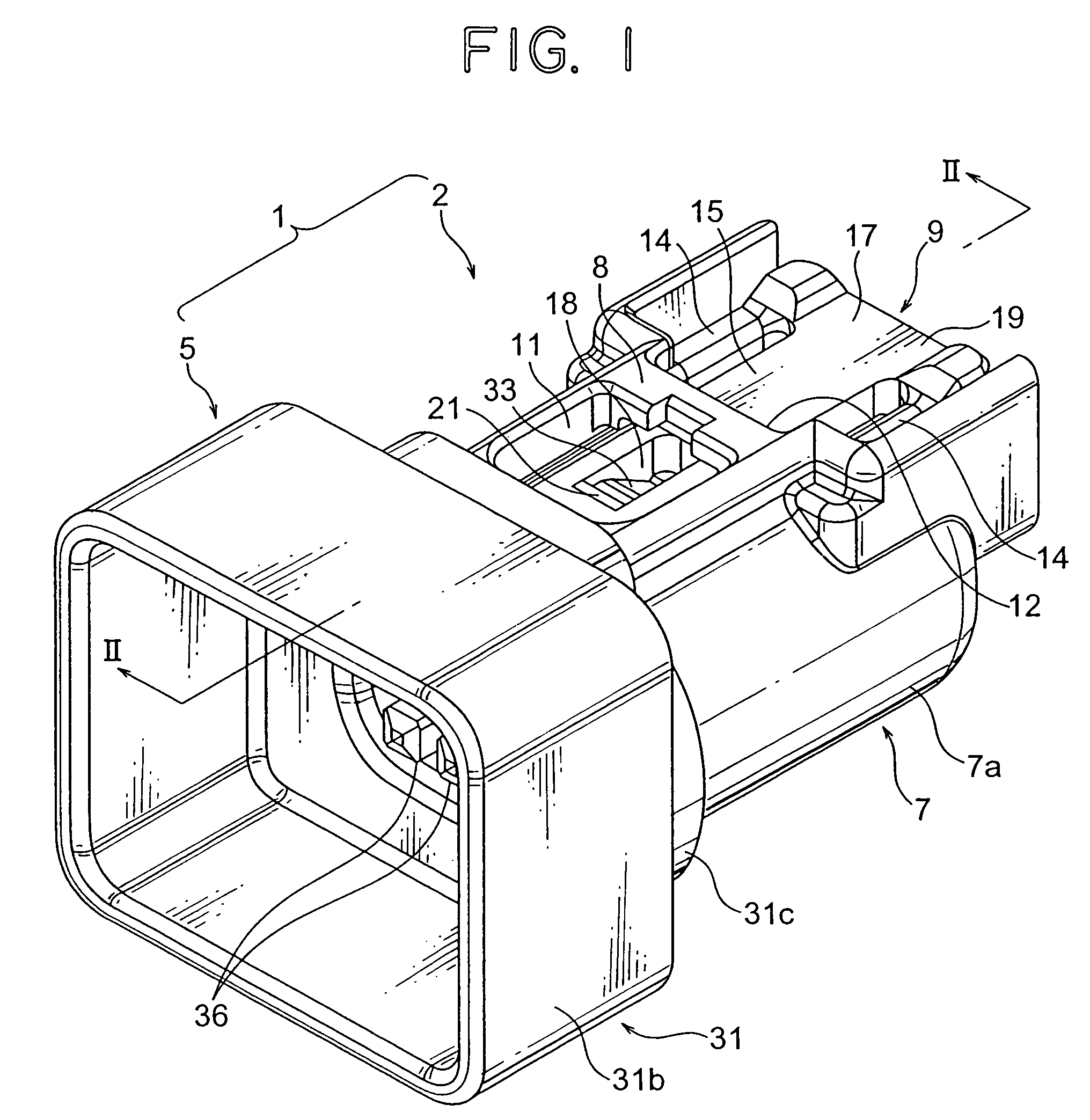
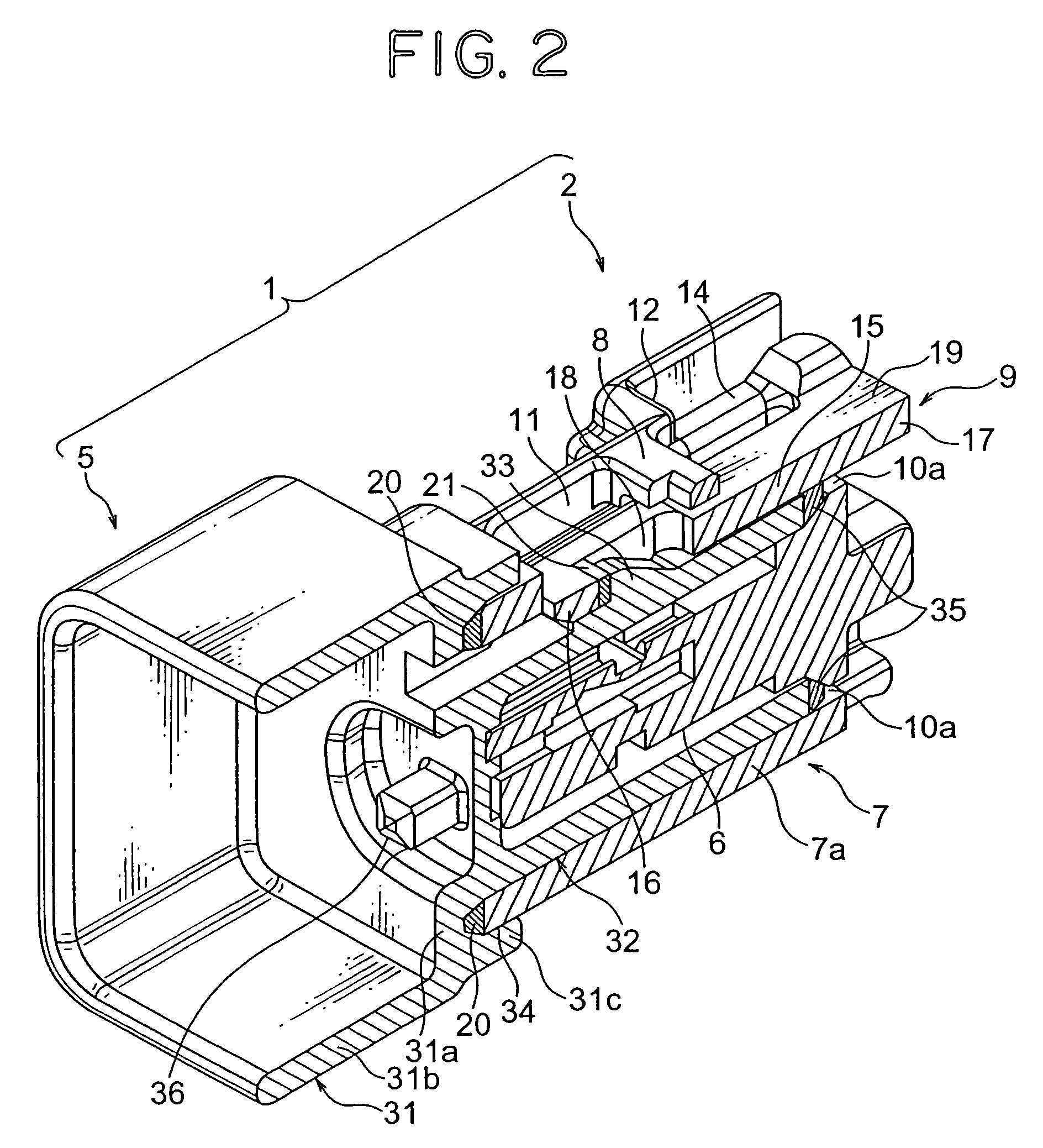
[0031]In the following, a connector according to the first preferred embodiment of the present invention will be explained with reference to FIGS. 1-8. As shown in FIGS. 1 and 2, a connector 1 according to the first preferred embodiment of the present invention includes a male connector housing 2 (hereinafter, male housing 2) and a female connector housing 5 (hereinafter, female housing 5).

[0032]In the first preferred embodiment, the male housing 2 corresponds to the first connector housing described in the claims and the female housing 5 corresponds to the second connector housing described in the claims. An outer housing 7 (explained later) of the male housing 2 corresponds to the hood part described in the claims, a body part 32 (explained later) of the female housing 5 corresponds to the terminal receiving part described in the claims, and a groove 34 (explained later) of the female housing 5 corresponds to the groove part described in the claims.

[0033]The male housing 2 is made...


PUM


Abstract

A connector including: a first connector housing having a tube-shaped hood part; a second connector housing to be fitted to the first connector housing; and a groove part provided on the second connector housing, wherein a terminal receiving part of the second connector housing is positioned in the hood part so that the first and second connector housings are fitted to each other, wherein an end part of the hood part enters the groove part when the first and second connector housings are fitted to each other.

Description

BACKGROUND OF THE INVENTION[0001](1) Field of the Invention[0002]The present invention relates to a connector having a vibration-resisting structure.[0003](2) Description of the Related Art[0004]A motor vehicle mounts various electronic instruments which are connected to the motor vehicle and other electronic instruments through a wiring harness. The electronic instruments are connected to the wiring harness when connectors of the electronic instruments are coupled with those of the wiring harness.[0005]The connector includes a connector housing and a terminal fitting to be received in the connector housing. When the connectors are coupled with each other, the respective terminal fittings in the connector housing are electrically connected to each other. Then, the wiring harness transmits electric power, control signals and so on to the electronic instruments.[0006]Such a connector may be often used under a severe condition of vibration such as a condition in an engine room. In such...

Claims


Application Information

Patent Timeline
Patent Type & Authority Patents(United States)
IPC IPC(8): H01R13/52
CPCH01R13/6272
Inventor AZUMA, KEIKOTORII, CHIEKOKATSUURA, TOMOMI
Owner YAZAKI CORP
Why Eureka
Try Eureka