Dual channel spatially adaptive CFAR

a spatial adaptive and dual channel technology, applied in the field of radar improvement, can solve the problem of achieve the effect of small impact on overall false alarm rate and low loss associated with parallel channels

Active Publication Date: 2010-01-05
TELEPHONICS
View PDF21 Cites 8 Cited by
  • Summary
  • Abstract
  • Description
  • Claims
  • Application Information

AI Technical Summary

Benefits of technology

[0011]It is a further object of the invention to eliminate most CFAR loss in a radar system so that enhanced target detection performance can be achieved at all aspect angles relative to the wind direction.
[0013]The present invention is directed to a dual channel spatially adaptive constant false alarm rate detection method, apparatus and system. The present invention provides CFAR gain in spatially correlated sea clutter and low CFAR loss in uncorrelated sea clutter. The present invention is capable of providing a means of detecting targets of a plurality of sizes from small point targets to large extended targets. Small point targets include but are not limiter to targets of the size of a periscope, raft and person in the water, etc. Larger extended targets include but are not limited to large surface ships, commercial vessels and combatants, etc. Optimum detection sensitivity in sea clutter environments is obtained in the present invention without sacrificing the ability to simultaneously detect small point target and large extended targets. The present invention has the ability to adapt automatically to sea clutter variations with look angle relative to the wind / swell direction.
[0016]For the case where the background is spatially correlated, the CFAR Gain Channel provides the best probability of detection (Pd). For the case of uncorrelated backgrounds and extended targets, the Main Channel provides the best Pd. The output of each channel is fused by a hit correlation function resulting in a stream of combined hits to be processed by the target centroiding function. With the DF property holding a constant false alarm rate, the hit correlation function is performed using a simple range association process where detections from either channel are “or'ed” to form combined hits. The incorporation of parallel channels has a small impact on overall false alarm rate however since the false alarms from the two channels are highly correlated so the combined false alarm rate after the fusion process is much less than two times the single channel false alarm rate. Therefore, the loss associated with the parallel channels is low.

Problems solved by technology

Therefore, the loss associated with the parallel channels is low.

Method used


Image

  • Dual channel spatially adaptive CFAR
  • Dual channel spatially adaptive CFAR
  • Dual channel spatially adaptive CFAR

Examples


Embodiment Construction

[0019]The following is an example of one embodiment of the present invention. The following describes a method, system and apparatus for implementing CFAR gain in correlated sea clutter while maintaining low CFAR loss in uncorrelated background areas. The embodiment also maintains the ability to simultaneously detect large targets and small targets as well as detect anomalies in the background region caused by land returns and nearby target returns. The method is applicable towards a wide range of maritime surveillance radars as long as the range resolution is sufficiently small relative to the sea clutter spatial correlation.

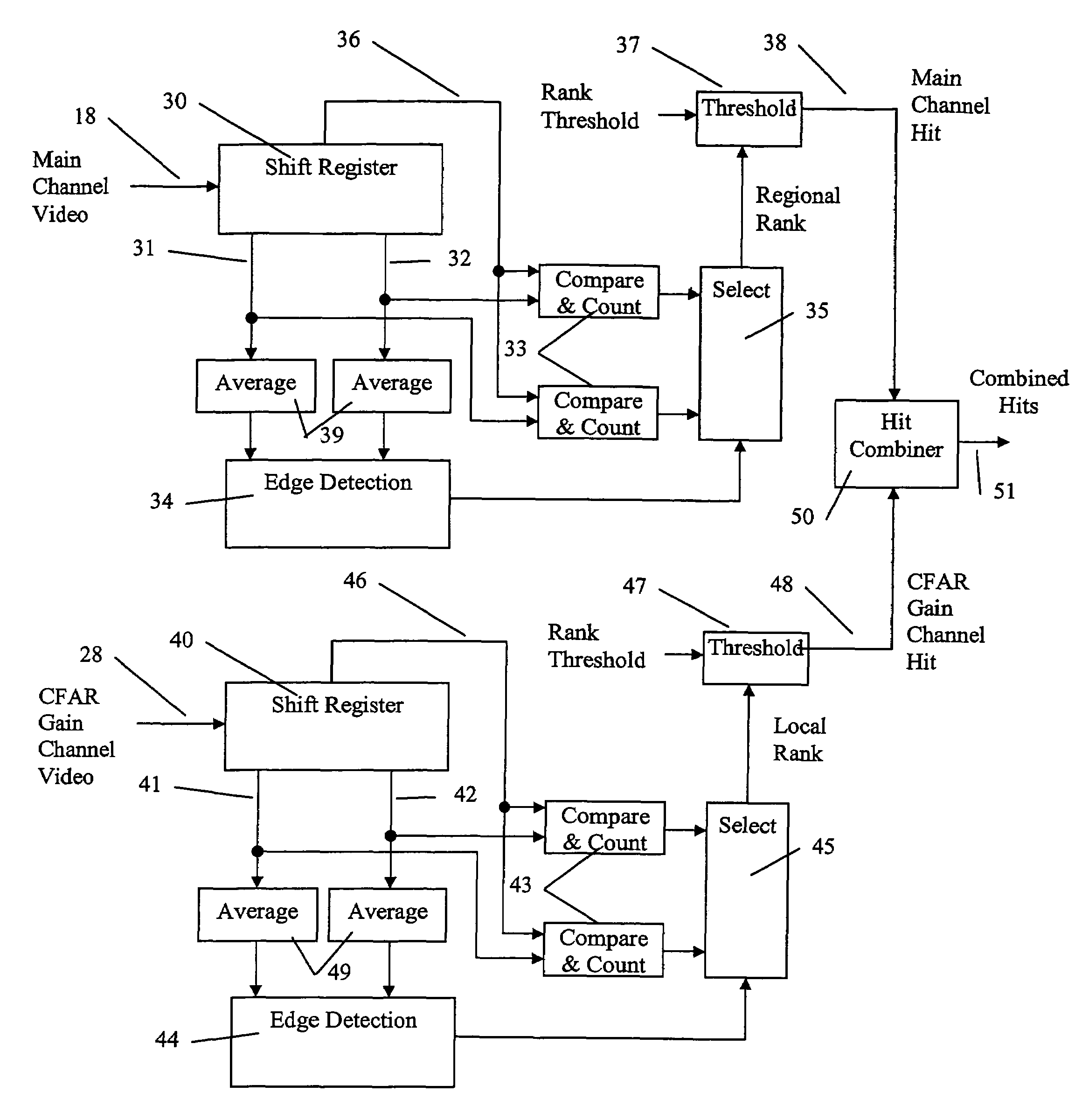
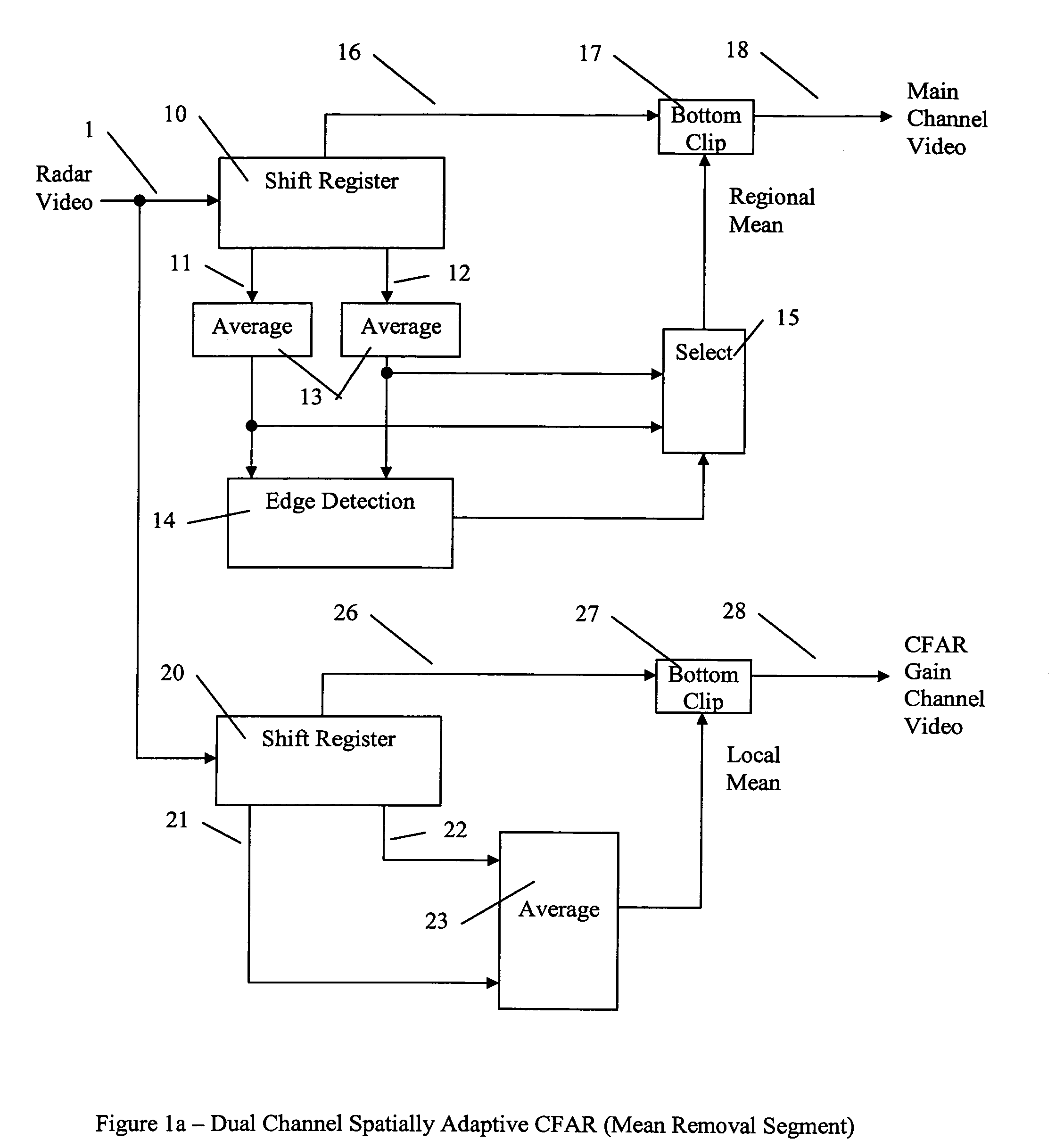
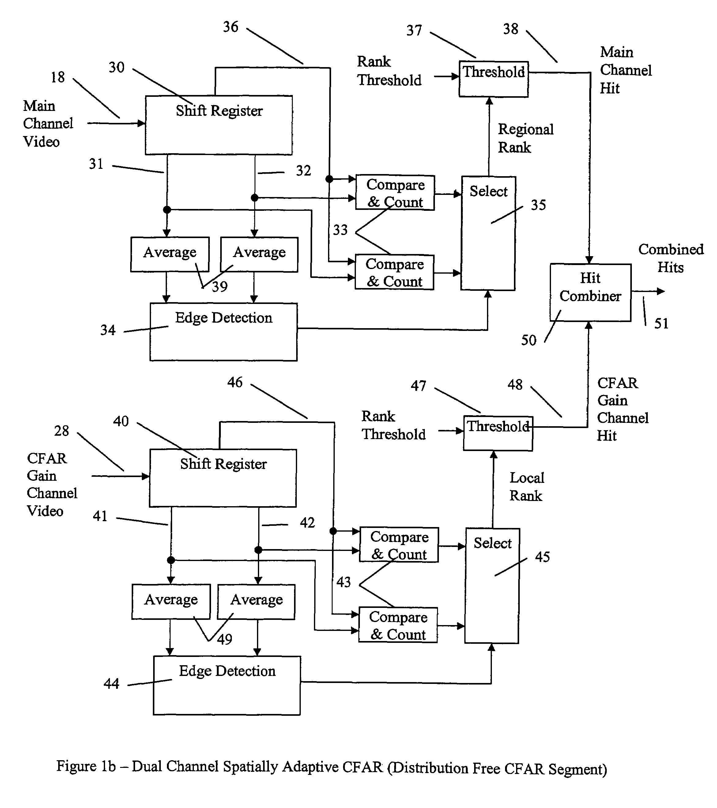
[0020]An example of the present invention is illustrated in FIG. 1. FIG. 1 shows two parallel processing channels performed in XILFNX on the Signal Processor Interface (SPI) card. The input radar video signal 1 is applied to two or more shift registers 10 and 20. One shift register 10 is sized to cover a large regional area while a second shift register 20 is s...


PUM


Abstract

A system for reducing CFAR loss due to sea clutter is disclosed. The system includes a first channel tuned for CFAR gain in a spatially correlated background and a second channel tuned for low CFAR loss in spatially uncorrelated backgrounds. Each of the channels employs a distribution free CFAR using rank ordered statistics to establish a constant false alarm rate. The output of each channel is fused by a hit correlation function and the stream of combined hits is processed by a target centroiding function.

Description

[0001]This application claims priority on U.S. Provisional Patent Application Ser. No. 60 / 627,652 filed Nov. 12, 2004 the disclosures of which are incorporated herein by reference.FIELD OF THE INVENTION[0002]The present invention is directed to improvements in radar and in particular improvements in reducing CFAR loss due to sea clutter.BACKGROUND OF THE INVENTION[0003]Radar backscatter from an ocean surface is commonly referred to as sea clutter. Any radar backscatter not due to the scattering from an ocean surface can be considered a potential target. The amplitude statistics of clutter have been modeled by Rayleigh, log-normal, contaminated-normal, Weibull, log-Weibull and K-distributions. Maritime surveillance radar relies on non-coherent processing techniques and the amplitude statistics of the sea clutter backscatter determines radar sensitivity and false alarm performance.[0004]In one type of surveillance radar system designed to detect low radar cross section targets such as...

Claims


Application Information

Patent Timeline
Patent Type & Authority Patents(United States)
IPC IPC(8): G01S7/292
CPCG01S7/2921
Inventor ONORATO, JAMES
Owner TELEPHONICS
Why Eureka
Try Eureka