Component brush system

Inactive Publication Date: 2010-01-12
BENTLY JOHN F
View PDF33 Cites 6 Cited by
  • Summary
  • Abstract
  • Description
  • Claims
  • Application Information

AI Technical Summary

Benefits of technology

[0006]The present invention is directed to avoiding one or more of the just discussed shortcomings. More particularly, the invention concerns a new component brush system that can assist in cleaning ducts, chimneys and the like. For example, this advantageous to enable replacement of components that tend to wear out sooner than others. Also, th

Problems solved by technology

Most air duct cleaners use vacuum equipment to induce rapid airflow within ductwork or chimneys, creating a tendency for loose dust or debris to be drawn along with the air.
However, this rapid airflow does not remove dust or unwanted material which has become settled or lodged on interior surfaces.
Such debris often builds up gradually over time, and has frequently formed a cohesive “pad” which cannot be removed by rapid airflow alone.
While using nozzles alone does dislodge some of the material and does break up “pads” of material on the bottom of ductwork, thus allowing some of the unwanted material to be drawn away by rapid airflow, such nozzles do not, always and/or

Method used


Image

  • Component brush system
  • Component brush system
  • Component brush system

Examples


Example

[0029]It should be noted that the drawings are not drawn to scale, and the sizes of the components shown and their features could be varied as desired, as long as otherwise consistent with the teachings herein.

DETAILED DESCRIPTION OF THE INVENTION

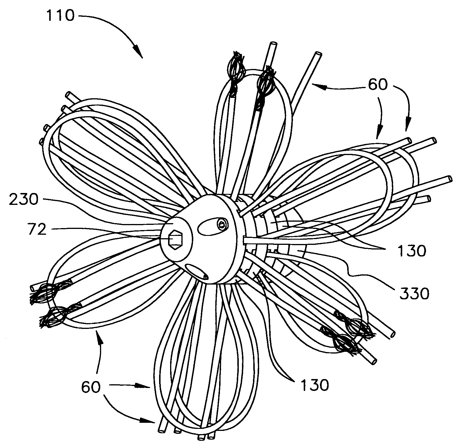
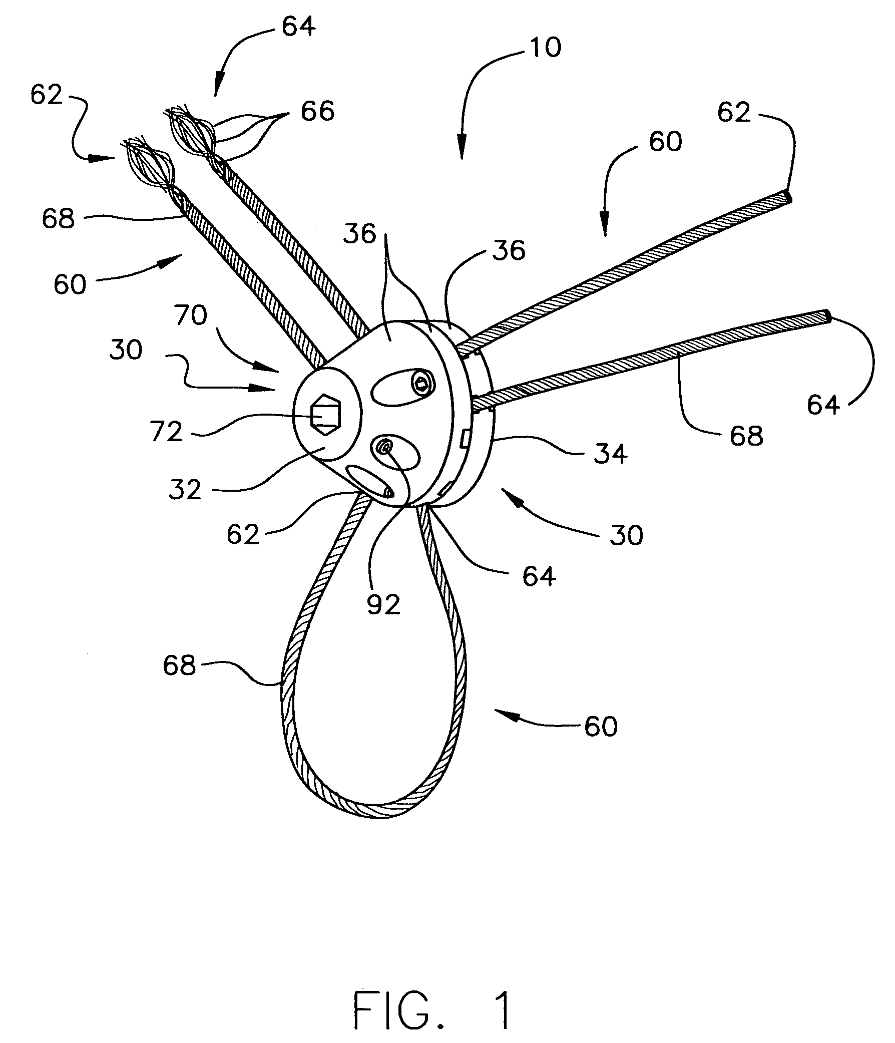
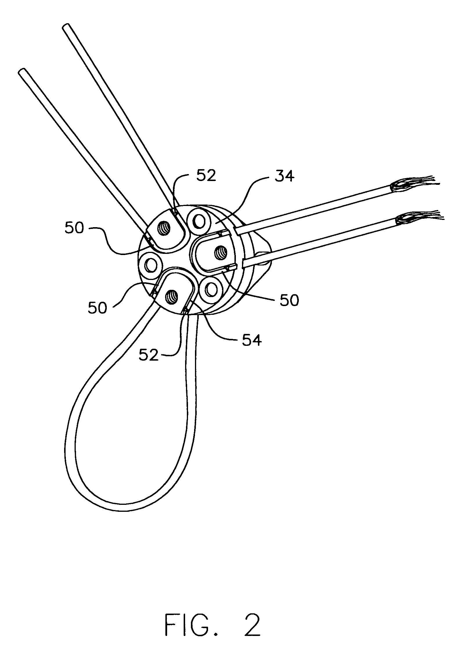
[0030]Referring to the Figures, and particularly FIGS. 1-7 inclusive and 15, for example, there is seen a component brush system 10 for use with a drive shaft, such as drive shaft portion 22. The brush system includes at least two connectable-disconnectable members 30. Each connectable-disconnectable member has a top surface 32, a bottom surface 34 and a middle 36 sandwiched between the top and bottom surfaces. At least one of the connectable-disconnectable members has at least one groove 50 disposed in at least a portion of at least one of its top or bottom surfaces 32, 34. The at least one groove is located between the connectable-disconnectable members when the connectable-disconnectable members are connected together. the system also in...


PUM


Abstract

A component brush system for use with a drive shaft, including at least two connectable-disconnectable members. Each connectable-disconnectable member has a top surface, a bottom surface and a middle sandwiched between the top and bottom surfaces. At least one of the connectable-disconnectable members has at least one groove disposed in at least a portion of at least one of its top or bottom surfaces. The groove is located between the connectable-disconnectable members when they are connected together. The system includes at least one elongate flexible cleaning member. At least a portion of the cleaning member is located within the groove and is secured in place between the connectable-disconnectable members and a remainder of the cleaning member extends away therefrom. At least one the connectable-disconnectable members includes a drive shaft joint where the drive shaft is removably connectable with the connectable-disconnectable member.

Description

PRIOR APPLICATION[0001]This application claims the benefit of U.S. Provisional Application No. 60 / 545,348 filed Feb. 17, 2004.BACKGROUND OF THE INVENTION[0002]Generally, this invention relates to a brush for use with a drive shaft, for example, to assist in removing undesirable dust, dirt and other debris from remote locations, specifically for dislodging such dust, dirt and other debris from areas which are difficult to reach, and therefore require special means to clean.[0003]For dislodging dust or unwanted debris from remote, difficult to reach locations, such as the interior of air ducts or chimneys, many different means have been employed. Most air duct cleaners use vacuum equipment to induce rapid airflow within ductwork or chimneys, creating a tendency for loose dust or debris to be drawn along with the air. However, this rapid airflow does not remove dust or unwanted material which has become settled or lodged on interior surfaces. Such debris often builds up gradually over ...

Claims


Application Information

Patent Timeline
IPC IPC(8): A46B13/00
CPCA46B3/08A46B13/003A46D1/00A46B2200/3013A46B2200/3073
Inventor BENTLY, JOHN F
Owner BENTLY JOHN F
Why Eureka
Try Eureka