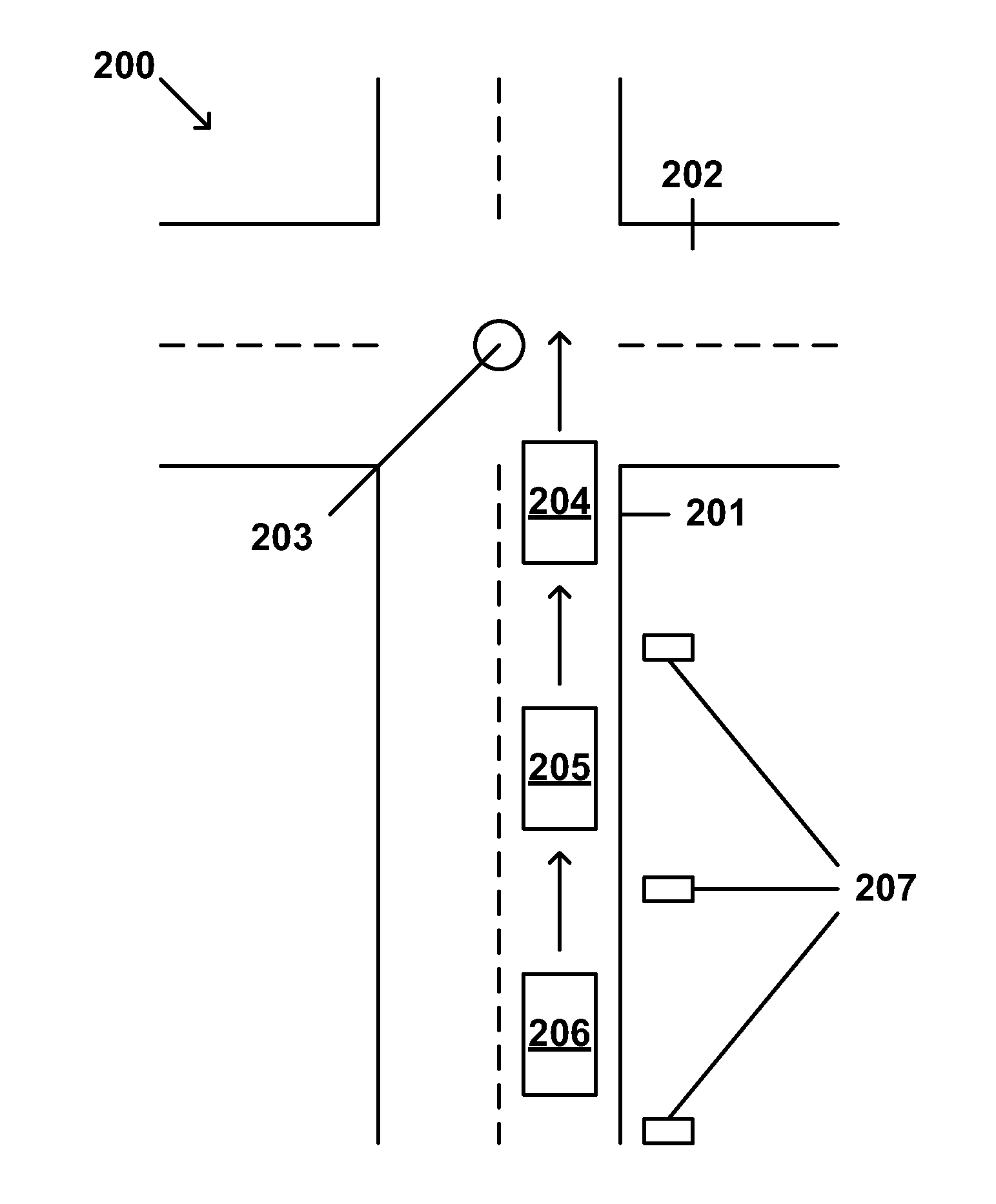
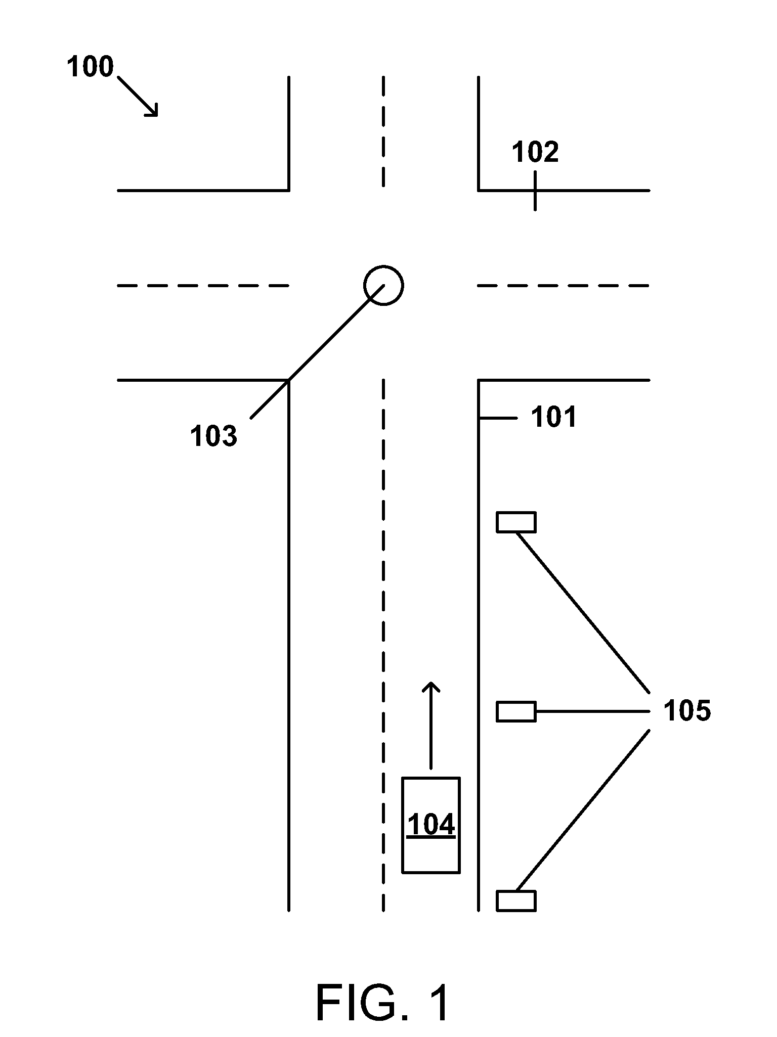
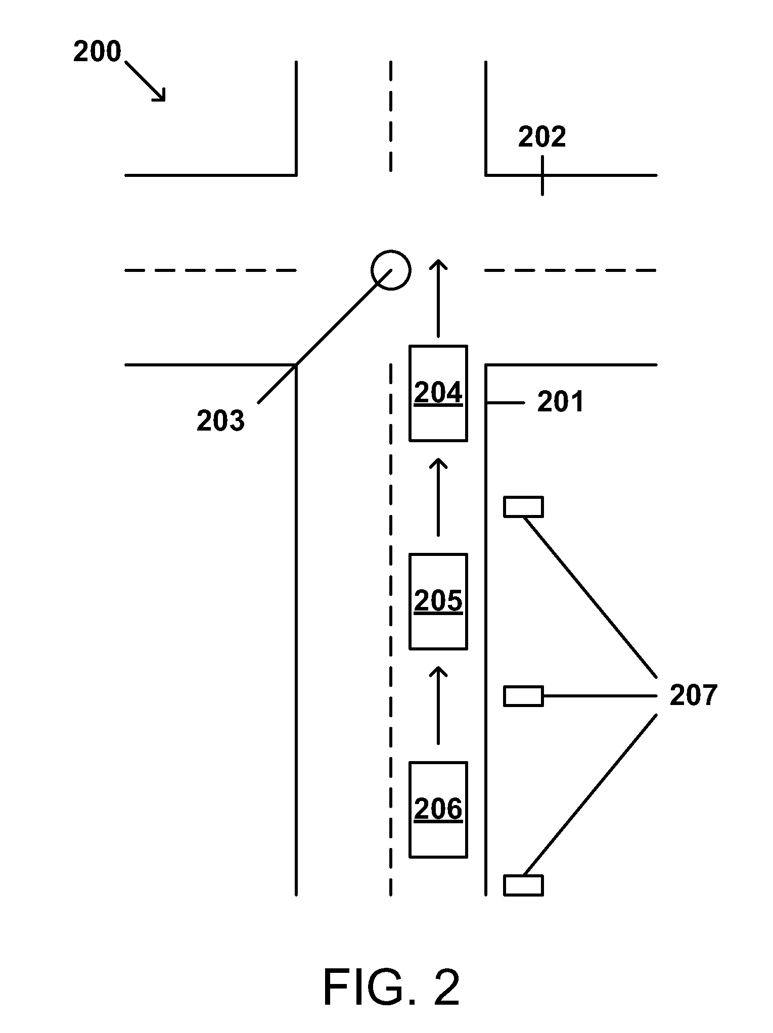
[0004]This disclosure provides a variable speed limit sign that can be used in conjunction with a centrally controlled traffic control device to provide a traffic
control system that can (1) reduce energy use by having vehicles avoid stopping at a traffic light, (2) reduce pollution by reducing energy use, (3) condition drivers to drive at the suggested speed by guaranteeing them a
green light at the next intersection (4) make driving more pleasurable and
safer by eliminating the uncertainty of making the next light, (5) eliminating the urge to speed to make the next light, (6) direct drivers drive in
platoon fashion at the controlled intersections, arriving slightly after the light turns green, and exiting slightly before the light turns red, (7) create a simple, economical, and decentralized
traffic system where each component is autonomous and reliable, (8) eliminate the annoying and dangerous cognitive dissonance that arises in the driver when the speed limit and the timing of lights are at
odds with each other, and (9) reduce congestion by increasing
traffic flow.
[0005]This disclosure allows drivers, who obey displayed, variable speed signs, to drive through an
urban area without stopping for traffic lights. The disclosure also teaches how to build an economical and reliable
system that can be implemented without the expense and complexity
wired communication or
radio frequency devices, sensors, or reactive or interactive real time computer controlled systems. This disclosure also prescribes a precise, simple, minimally directive, intuitive
system for drivers to follow. This disclosure teaches a means of guaranteeing drivers leaving one intersection, a
green light at the next. This disclosure displays to all drivers passing, a single speed to drive to reach the next intersection in time for a scheduled
green light. The speed displayed will result in all drivers converging in a target area, near the next traffic light controlled intersection, in
platoon fashion, when the light turns green. This disclosure is not hindered by weather, hills, obstacles, or distance. The only thing the driver needs to learn is to follow the posted speed limit. By lessening the number of stops, driver's mileage will increase; they will be happier, they will drive the prescribed speed, emissions will fall, and traffic will move more smoothly through intersections, a given road will be able to carry more traffic.
[0006]By using variable speed signs and precise, programmed, predictable schedules based in
universal time, as well as giving drivers a single precise speed to travel, drivers are more likely to follow the posted speed. This disclosure follows a simple repetitive pattern: (1) go through an intersection; (2) read the speed sign; (3) drive that speed; and (4) the next light will be green as you approach. Additionally, by using precise traffic light schedules, and variable speeds, it will be possible to program an entire grid so that cross traffic may move without encountering red lights. By giving the driver a guarantee of a green light at the next intersection, most rational people will simply drive that speed. Conversely, by not driving the posted speed, a driver is probably going to hit a
red light, and thus will have an incentive not to speed above the displayed speed directive. By guaranteeing the driver of an upcoming green light, drivers will become conditioned, remain calm, and drive predictably at legal speeds.
[0007]This disclosure uses precise programmed predictable schedules that are programmed and scheduled in
universal time. As such, different traffic control jurisdictions can easily share scheduling information so that their traffic lights may be coordinated. By using such schedules a
computer program will be able to model traffic flows in a grid, so that drivers can drive without stopping.
[0008]This disclosure does not require that the individual components communicate with each other. Each variable speed limit sign is a programmed, stand-alone unit that is autonomous from the traffic signals or other variable speed limit signs. Thus, a traffic
control system that utilizes the variable speed limit sign is relatively simple, consumes little power, relatively tamperproof, economical, quickly installed, and robust. All that need be done is replace, or modify and reprogram existing computerized traffic light controllers. Then install specialized, stand alone, pre-programmed variable speed limit signs, with specialized controllers displaying the correct legal speed necessary to drive so as to make the next green light.
[0024]In one embodiment, a second display output provides the speed that will provide a left hand turn or a right hand turn at the next traffic controller.


