Breather device for an engine

a technology for fuel tanks and fuel tanks, which is applied in the direction of combustion engines, crankcase ventilation, machines/engines, etc., can solve the problem of not having the oil-separation function required for using the supercharger, and achieve the effect of ensuring the oil-separation function

Active Publication Date: 2010-01-12
KUBOTA LTD
View PDF8 Cites 11 Cited by
  • Summary
  • Abstract
  • Description
  • Claims
  • Application Information

AI Technical Summary

Benefits of technology

[0024]<Effect> It is possible to assuredly obtain the oil-separation function required for using the supercharger.
[0025]As exemplified in FIG. 2(A), before the blow-by gas flows into the breather chamber 3, the blow-by gas that has flowed from the front-stage breather-chamber inlet 33 into the front-stage breather chamber 28 floats up around the preliminary valve-seat peripheral wall 22 and the preliminary breather-passage peripheral wall 24, thereby allowing the oil mist contained in the blow-by gas to condense on the surfaces of the preliminary valve-seat peripheral wall 22 and of the preliminary breather-passage peripheral wall 24 and then separate the oil. Further, the blow-by gas that has flowed from the breather-chamber inlet 21 into the breather chamber 3 floats up around the valve-seat peripheral wall 14 and the breather-passage peripheral wall 19, thereby allowing the oil mist contained in the blow-by gas to condense on the surfaces of the valve-seat peripheral wall 14 and of the breather-passage peripheral wall 19 and then separate the oil. As such, the oil-separation is performed doubly within the front-stage breather chamber 28 and the breather chamber 3. This ensures the oil-separation function required for using the supercharger 8 to be obtained.
[0026]<Effect> The front-stage breather chamber of the supercharged engine is also applicable to the naturally aspired engine.
[0027]As exemplified in FIG. 2(A), in the event that the breather-chamber peripheral wall 12 is removed from the breather-chamber attaching seat 11, the diaphragm valve 16 is attached to the breather-chamber attaching seat 11 and has its valve face 18 seated on the preliminary valve seat 23a. By removing the plug 27 from the preliminary breather outlet 25, the front-stage breather chamber 28 is available for the single-stage breather chamber provided with the diaphragm valve 16. Therefore, the front-stage breather chamber 28 is applicable to the naturally aspired engine which does not require a high oil-separation function.
[0028]<Effect> The naturally aspired engine can use the head cover as a part common to the engine of the present invention.
[0029]As exemplified in FIG. 2(A), the preliminary valve-seat peripheral wall 22 has the upper surface formed with the preliminary valve seat 23, and the diaphragm valve 16 is adapted to be attached to the breather-chamber attaching seat 11. When the diaphragm valve 16 is attached to the breather-chamber attaching seat 11, the preliminary valve seat 23 allows the valve face 18 of the diaphragm valve 16 to be seated thereon. In consequence, the naturally aspired engine can use the head cover 2 as a part common to the engine of the present invention.Invention of Claim 2

Problems solved by technology

There is a case where the oil-separation function required for using the supercharger is not available.

Method used


Image

  • Breather device for an engine
  • Breather device for an engine
  • Breather device for an engine

Examples


Embodiment Construction

[0050]Hereafter, an explanation is given for an embodiment of the present invention based on the drawings.

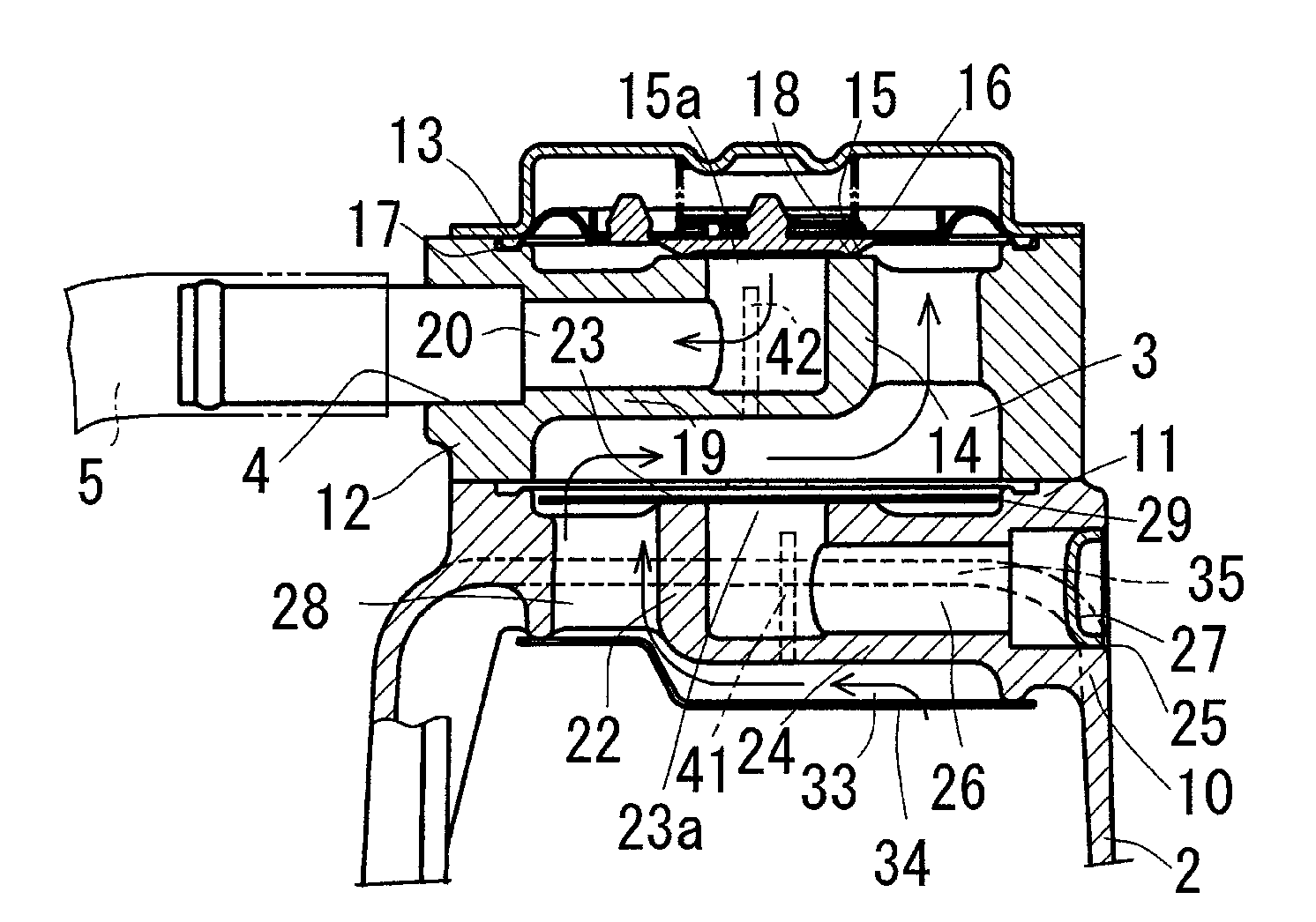
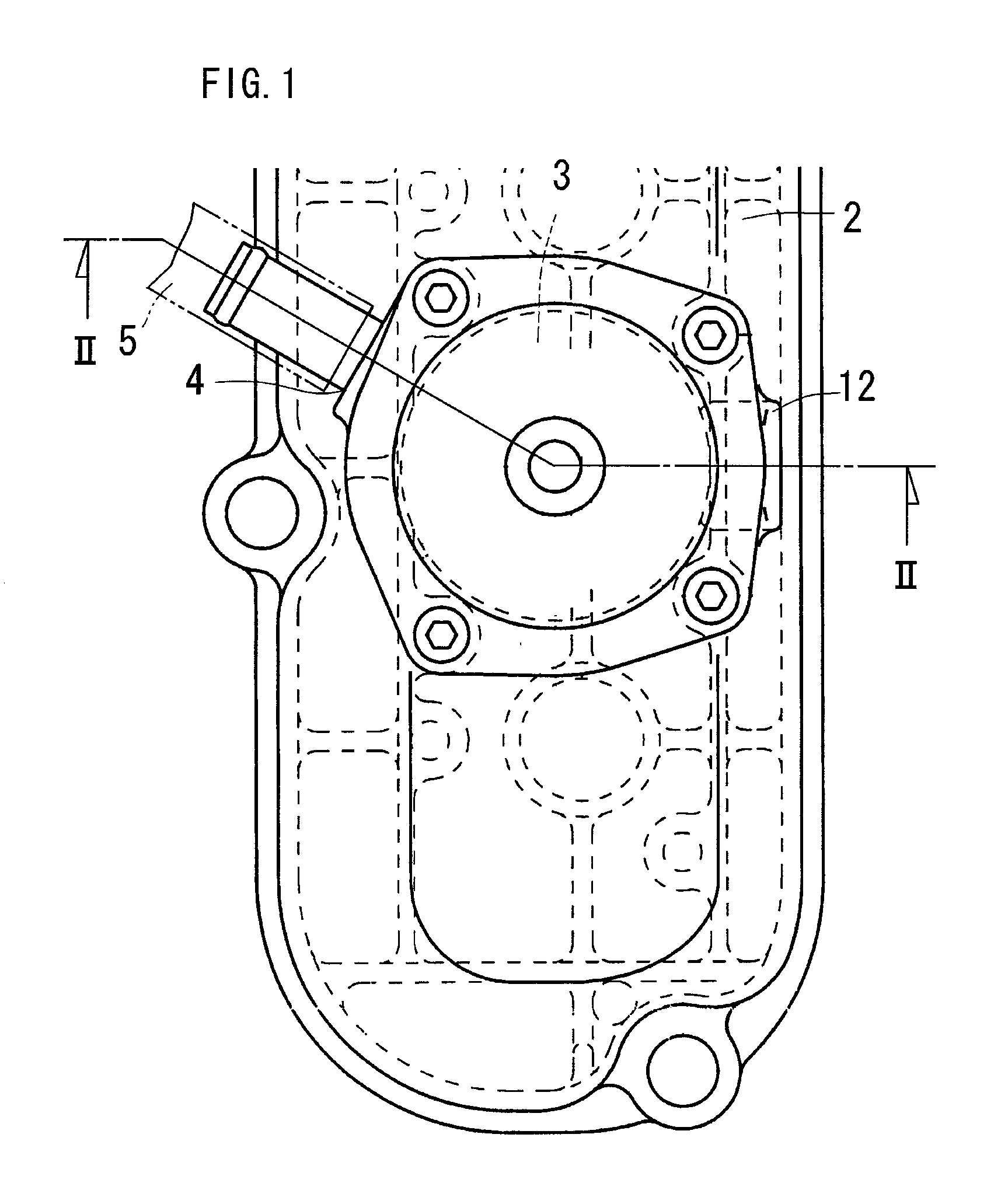
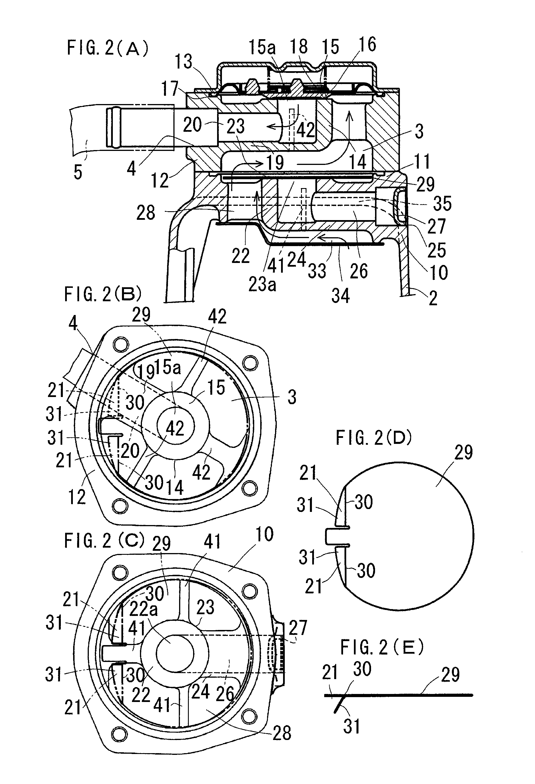
[0051]FIGS. 1 to 4 show a breather device for an engine according to the embodiment of the present invention. In this embodiment, an explanation is given for a breather device for a diesel engine.

[0052]The embodiment of the present invention is outlined as follows.

[0053]As shown in FIG. 3, the engine comprises a cylinder head 1 to one lateral side of which an exhaust manifold 36 is attached and to the other lateral side of which an intake manifold 37 is attached, respectively. A head cover 2 is attached onto the cylinder head 1. The head cover 2 is provided at its upper portion with a breather chamber 3 having a breather outlet 4, from which a breather pipe 5 is led out. The breather pipe 5 has a led-out end portion 6 connected to an air-intake route 7. Concretely, a supercharger 8 has an air-intake inlet 9 to which the led-out end portion 6 of the breather pipe 5 is connected. ...


PUM


Abstract

The blow-by gas that has flowed from a front-stage breather-chamber inlet (33) into a front-stage breather chamber (28) floats up around a preliminary valve-seat peripheral wall (22) and a preliminary breather-passage peripheral wall (24) and flows from a breather-chamber inlet (21) into a breather chamber (3). When a breather-chamber peripheral wall (12) is removed from a breather-chamber attaching seat (11), a diaphragm valve (16) is attached to the breather-chamber attaching seat (11) and has a valve face (18) seated on a preliminary valve seat (23), and a plug (27) is taken out of a preliminary breather outlet (25), from which a breather pipe (5) is led out, thereby enabling the front-stage breather chamber (28) to be used for a single-stage breather chamber provided with the diaphragm valve (16).

Description

BACKGROUND OF THE INVENTION[0001]1. Technical Field[0002]The present invention relates to a breather device for an engine, and more particularly concerns a breather device for an engine, which can assuredly obtain the oil-separation function required for using a supercharger.[0003]2. Background Art[0004]A conventional example of the engine breather devices comprises a cylinder head onto which a head cover is attached, the head cover being provided at a ceiling wall with a breather chamber having a breather outlet, from which a breather pipe is led out, this breather pipe having a led-out end portion connected to an air-intake route (for example, see Patent Literature 1) as well as the present invention.[0005]The engine breather device of this type separates oil from the oil mist contained in the blow-by gas within the breather chamber and flows the remaining oil mist with the blow-by gas into the air-intake route, whereby the oil mist is prevented from flowing out of the breather de...

Claims


Application Information

Patent Timeline
Patent Type & Authority Patents(United States)
IPC IPC(8): F01M13/00
CPCF01M13/0011F01M13/022F01M13/0416F01M2013/027F01M2013/0461
Inventor YOSHIDA, KOZOMANABE, HIROSHIOKUDA, MITSUGU
Owner KUBOTA LTD
Why Eureka
Try Eureka