Flushing device and method of flushing an annular space

a technology of flushing device and annular space, which is applied in the direction of fluid removal, wellbore/well accessories, sealing/packing, etc., can solve the problems of increasing the complexity of the network, increasing the length of the extraction activity in the oil and gas industry, and new challenges in the field of well boring, etc., to achieve the effect of increasing the reliability

Inactive Publication Date: 2010-01-12
DRILLING SOLUTIONS
View PDF9 Cites 15 Cited by
  • Summary
  • Abstract
  • Description
  • Claims
  • Application Information

AI Technical Summary

Benefits of technology

[0036]When the flushing member is in use, the pressure acting upon the plunger by the fluid flowing through the passage of the flushing device is greater than the biasing force exerted thereupon. This results in the locking member being forced outward and engaging with the first or second groove, depending upon the condition of the flushing device. Any downward movement exerted upon the inner sleeve relative to the outer sleeve will result in the locking member abutting a lower face of the groove to prevent further downward movement of the inner sleeve, preventing the flushing device from unintentionally changing between the closed and opened conditions.
[0038]Preferably the inner sleeve and outer sleeve define a cavity therebetween. The cavity may be filled with a lubricating fluid such as oil, providing an oil chamber. Preferably the indexing mechanism operates in the oil chamber. Preferably the oil chamber is sealed from the passage such that no slurry can contaminate the oil. This ensures that the slurry does not interfere with the operation of the flushing device, increasing its reliability.
[0039]The flushing device may also comprise means to balance and cushion the movement between the inner and outer sleeve. The means to balance and cushion may be in the form of a floating piston. The floating piston may equalise the pressure within the oil chamber.
[0043]a locking mechanism operable between the inner and outer sleeves, and having engaging and releasing conditions, the locking mechanism being biased towards the release condition and being responsive to fluid pressure in the passage for movement against the influence of the bias into the engaging condition, whereby the locking mechanism, when in the engaging condition couples the inner sleeve to the outer sleeve to prevent substantial downward movement of the inner sleeve relative to the outer sleeve and preventing the flushing device from unintentionally changing its condition between open and closed.
[0049]allowing the fluid to pass through the flushing device causing the locking mechanism to lock the inner sleeve to the outer sleeve, such that substantial downward movement of the inner sleeve relative to the outer sleeve in said first direction is prevented, wherein a percentage of the fluid is diverted from the passage to pass to the annular space through the flushing outlet to assist in cleaning the bore.

Problems solved by technology

As well paths in exploration and extraction activities in the oil and gas industries become increasingly longer and the network more complicated, new challenges are constantly faced in the area of well boring.
One of these challenges is in respect of maintaining suitable conditions for the operation of the drill head or bit to cut through the medium.
Failure to remove the cuttings, or a suitable percentage of the cuttings, can cause equipment failure, resulting in costly down time and may even result in the equipment being irretrievable.
A build up of cuttings may result due to a reduction in the flow of slurry to and from the drill head, it may place unnecessary loads on the drill head and stem assembly, and may also cause the drill head to be wedged or jammed in the bore.
Furthermore, with the increase in use of horizontal bores in well networks, a build up of cuttings on the lowermost, or bottom surface of the bore may cause side displacement of the drill head, resulting in the bore being drilled in a new and incorrect direction.
Increasing the flow rate of the slurry and hence the return rate of the slurry to the surface does not sufficiently solve the problem.
This not only inhibits the drilling process but is also problematic when introducing pipe linings.
Also, during subsequent cementing, additional problems are experienced if the hole is not relatively clear.
As the annular space between the drill stem assembly and the bore wall is particularly narrow, it is often the cause of packing or wedging of cuttings in this region.
If the compressive or tractive force is not constantly applied to the flushing device, the flushing device may automatically, and undesirably move to the alternate condition.
The manner in which these parts are coupled together result in high concentrations of forces at this junction.
These concentrations often lead to failures at this interface, requiring costly repairs to be made.
A further deficiency in this device is in relation to the bleed holes located on the outer wall of the tool.
These bleed holes allow cuttings to ingress into the flushing device, contaminating the various parts within the flushing device, which may result in tool failure.
This is undesirable during a drilling operation.
Furthermore, this particular device is constructed such that the major moving components operate in the slurry, leading to reliability problems.
Also, similar to U.S. Pat. No. 6,161,632, breather ports located on the apparatus allow cuttings to enter the device, causing additional problems in relation to the reliability of the device.
Owing to the configuration of the device, hydraulic lock can occur resulting in a build up of pressure.

Method used


Image

  • Flushing device and method of flushing an annular space
  • Flushing device and method of flushing an annular space
  • Flushing device and method of flushing an annular space

Examples


Embodiment Construction

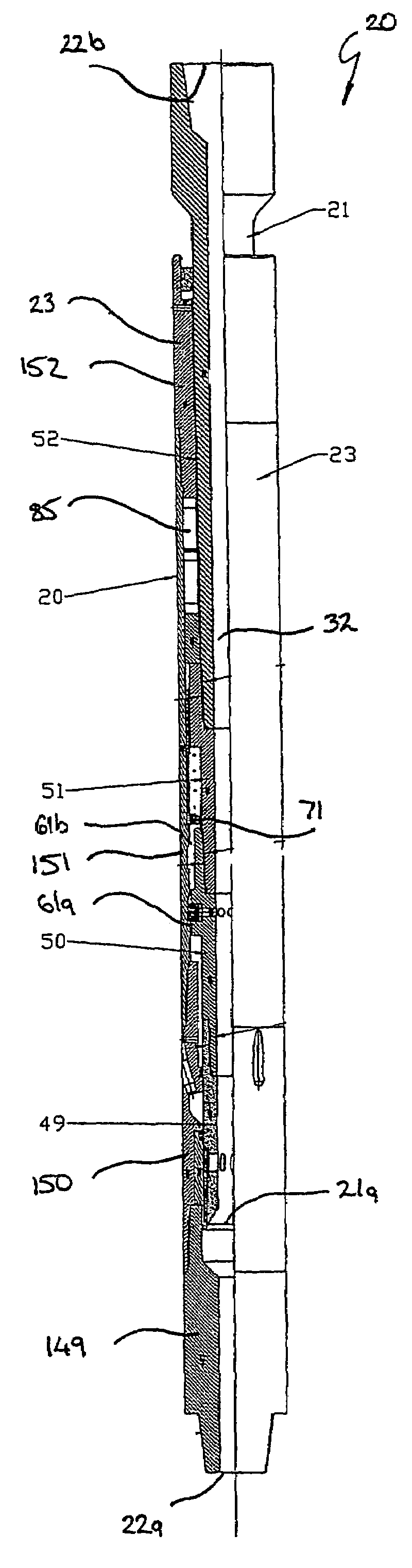
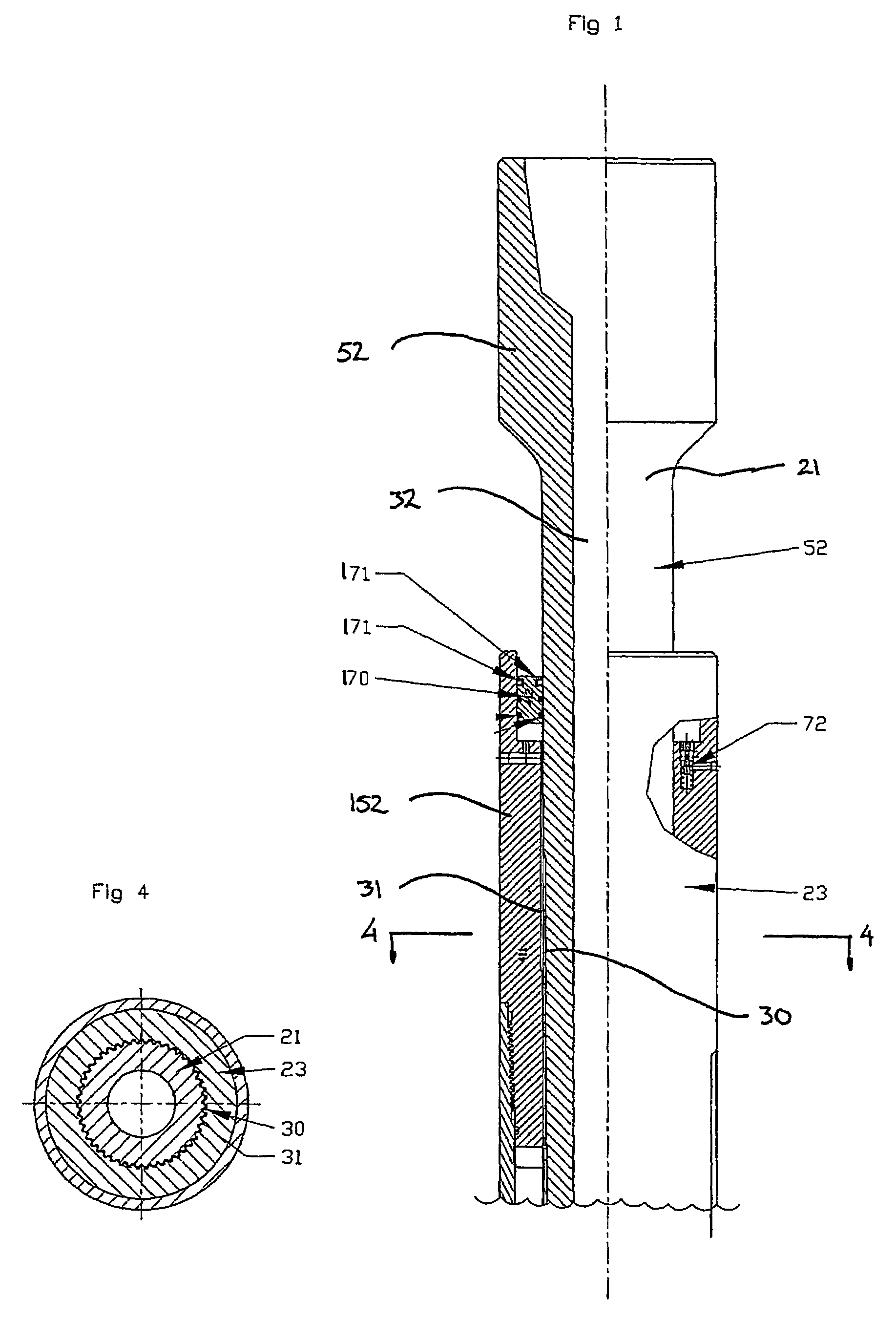
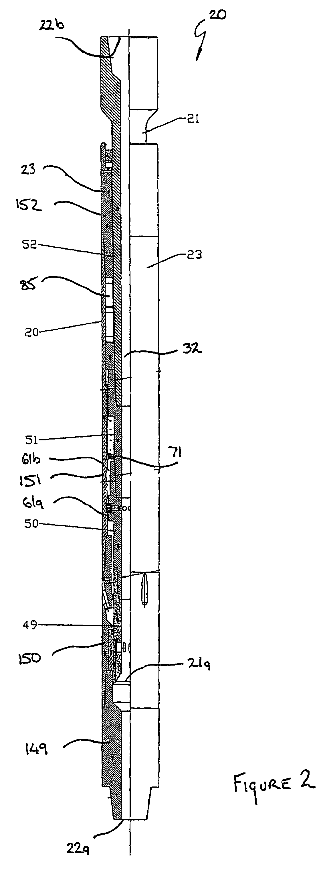
[0070]Referring to FIGS. 1 to 3, the invention according to an embodiment is a flushing device 20, comprising an outlet 22a, an inlet 22b, an inner sleeve 21 and an outer sleeve 23, which cooperate to provide a fluid passage 32.

Inner Sleeve

[0071]The inner sleeve 21 comprises a first inner portion 49 located at a first end 21a of the inner sleeve 21. The first inner portion 49 is secured through threading engagement to a second inner portion 50 which is secured through threading engagement to a third inner portion 51 which in turn is secured through threading engagement to a fourth inner portion 52. The fourth inner portion 52 defines the inlet 22b of the flushing device 20, and is adapted to be releasable incorporated in the drill stem assembly.

[0072]A plurality of seals 53a are positioned at the interface between each portion 49, 50, 51, 52 so as to prevent the leakage of fluid from the passage 32, through the threaded interface between each portion and into an oil chamber 53 (whic...


PUM


Abstract

A flushing device (20) comprising an inner sleeve (21), axially slidable relative to an outer sleeve (23). The inner (21) and outer (23) sleeves cooperate to define an inner passage (32) for the flow of a fluid, and are permanently coupled such that there is substantially no rotational movement between the two sleeves. The inner passage (32) has an inlet (22b) and an outlet (22a). The outer sleeve (23) has a plurality of flushing outlets (33) which, when the flushing device (20) is in an open condition allow fluid to be diverted from the inner passage (32). The flushing device (20) also comprises an indexing mechanism (80) which indexes between a first position, wherein the plurality of flushing outlets (33) are blocked from the internal passage (32) such that the flushing device (20) is in a closed condition, to a second position, wherein the plurality of flushing outlets (33) register with the internal passage (32) such that the flushing device (20) is in the open condition. When fluid flows through the flushing device (20), the flushing device (20) is configured such that it remains in the selected open or closed condition regardless of the forces acting thereupon.

Description

FIELD OF THE INVENTION[0001]The present invention generally relates to a flushing device for use in conjunction with a drilling head for the drilling of subsurface holes and wells. In particular the invention relates to a flushing device which assists in maintaining suitable conditions for a drill head to operate efficiently.BACKGROUND ART[0002]As well paths in exploration and extraction activities in the oil and gas industries become increasingly longer and the network more complicated, new challenges are constantly faced in the area of well boring. One of these challenges is in respect of maintaining suitable conditions for the operation of the drill head or bit to cut through the medium.[0003]When drilling well bores, a slurry, used to operate the drill head, is pumped from the surface through a drill stem assembly to the drill head. Upon reaching the end of the bore the slurry is caused to return to the surface, passing through the annular space between the sidewalls of the bore...

Claims


Application Information

Patent Timeline
Patent Type & Authority Patents(United States)
IPC IPC(8): E21B21/10E21B23/00E21B34/14E21B41/00
CPCE21B21/103E21B23/006E21B34/14E21B41/0078E21B34/142
Inventor BEGLEY, MAXWELL GRAHAMMUNSLOW-DAVIES, KEITH
Owner DRILLING SOLUTIONS
Why Eureka
Try Eureka