Motorcycle exhaust structure

a technology for exhaust pipes and motorcycles, applied in the direction of machines/engines, cycles, transportation and packaging, etc., can solve the problem of not being able to place a muffler under the crankcase, and achieve the effect of moving the body agilely and reducing the inertia for

Active Publication Date: 2010-01-12
HONDA MOTOR CO LTD
View PDF11 Cites 6 Cited by
  • Summary
  • Abstract
  • Description
  • Claims
  • Application Information

AI Technical Summary

Benefits of technology

[0004]In a situation where a muffler like the above known one is located under a crankcase, a relatively large and heavy muffler may be located in a lower portion of a vehicle body. This arrangement is suitable for an on-road motorcycle, which is requested to be able to move its body agilely by placing a heavy component in a position as low as possible in the body, thus reducing the inertia force when inclining the body left or right.
[0011]According to the first aspect of the present invention, the muffler is located ahead of the crankcase and behind the front wheel with the front suspension in its retracted position and above a lower end of the body frame. Therefore, the muffler can be near the head pipe. Therefore, when the vehicle body moves centering around the head pipe, the inertia force is reduced. Moreover, the minimum road clearance can be high, which is suitable for an off-road motorcycle.
[0012]In addition, when the front and rear of the vehicle body move vertically on an uneven road surface, since the muffler is near the engine, heavy components are concentrated in the vicinity of the center of the body. As a consequence, the inertia force is reduced, thereby decreasing vertical movement of the front and rear of the body.

Problems solved by technology

However, in an off-road motorcycle, since its cylinder should be upright and the minimum road clearance should be high in order to ensure that the engine is longitudinally short, it is impossible to place a muffler under a crankcase.

Method used


Image

  • Motorcycle exhaust structure
  • Motorcycle exhaust structure
  • Motorcycle exhaust structure

Examples


Embodiment Construction

[0026]An embodiment will now be described with reference to the accompanying drawings, wherein the same or similar elements will be identified with the same reference numeral throughout the several views.

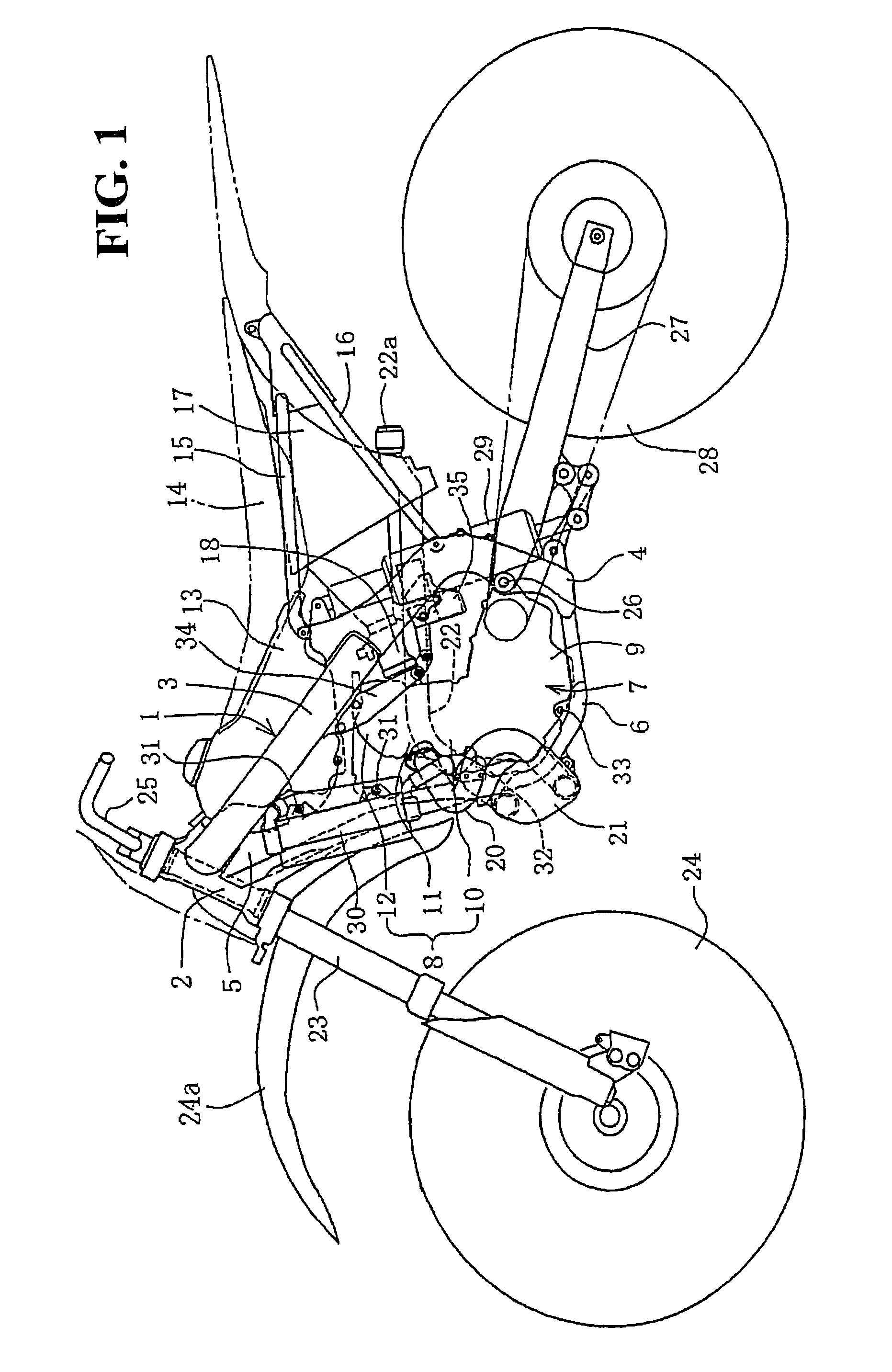
[0027]FIG. 1 is a side view of an off-road motorcycle to which a body frame structure according to this embodiment is applied. The body frame 1 of this motorcycle includes a head pipe 2, a main frame 3, a center frame 4, a down frame 5 and a lower frame 6, which are connected in a loop-like manner with an engine 7 held inside the loop. The down frame 5 and the lower frame 6 constitute a front frame in this application. The constituent parts of the body frame 1 are each made of appropriate metal materials such as aluminum alloy. The head pipe 2 and the center frame 4 are castings. The main frame 3 and the lower frame 6 are square pipe wrought products made by extrusion molding. The down frame 5 is a combination of a wrought product and a casting.

[0028]The main frame 3 extends straigh...


PUM


Abstract

To place a muffler in a front area to make it suitable for an off-road motorcycle, A down frame extending downward obliquely from a head pipe ahead of an engine and a lower frame connected with its lower end, extending backward under the engine, are provided. A muffler is located in the vicinity of the joint between the down frame and the lower frame where its rear surface is curved forward in a convex pattern along the down frame and the lower frame. An exhaust pipe extending from a cylinder head is almost S-shaped as seen sideways and its forward curved portion and lower backward curved portion are vertically arranged with its lower end connected with a lower portion of the muffler.

Description

CROSS-REFERENCE TO RELATED APPLICATIONS[0001]This nonprovisional application claims priority under 35 U.S.C. § 119(a) on Patent Application No. 2006-047582, filed in Japan on Feb. 23, 2006, the entirety of which is incorporated herein by reference.FIELD OF THE INVENTION[0002]The present invention relates to a motorcycle exhaust structure. In particular, the present invention relates to a motorcycle exhaust structure that is suitable for an off-road vehicle.DESCRIPTION OF BACKGROUND ART[0003]A motorcycle exhaust structure is known, wherein a main frame extending downward obliquely and backward from a head pipe supporting a front wheel is provided. A V-type engine is held under the main frame. An exhaust pipe extending from a cylinder of the engine is connected to a muffler divided into two portions before and after an oil pan under a crankcase. The rear muffler portion is larger than the front muffler portion (see JP-A No. 2004-26007).SUMMARY OF THE INVENTION[0004]In a situation wher...

Claims


Application Information

Patent Timeline
Patent Type & Authority Patents(United States)
IPC IPC(8): B62M7/04B62M7/02
CPCF01N13/08F01N2590/04F01N2340/04
Inventor ADACHI, EIJINOGUCHI, YUJI
Owner HONDA MOTOR CO LTD
Why Eureka
Try Eureka