Expandable motor home

Inactive Publication Date: 2010-01-12
LUDWICK ERIC
View PDF33 Cites 19 Cited by
  • Summary
  • Abstract
  • Description
  • Claims
  • Application Information

AI Technical Summary

Benefits of technology

[0009]Another object of the invention is to make efficient use of space

Problems solved by technology

The interior space of a motor home is limited by size restrictions on vehicles which use public roads.
A fixed second s

Method used


Image

  • Expandable motor home
  • Expandable motor home
  • Expandable motor home

Examples


first embodiment

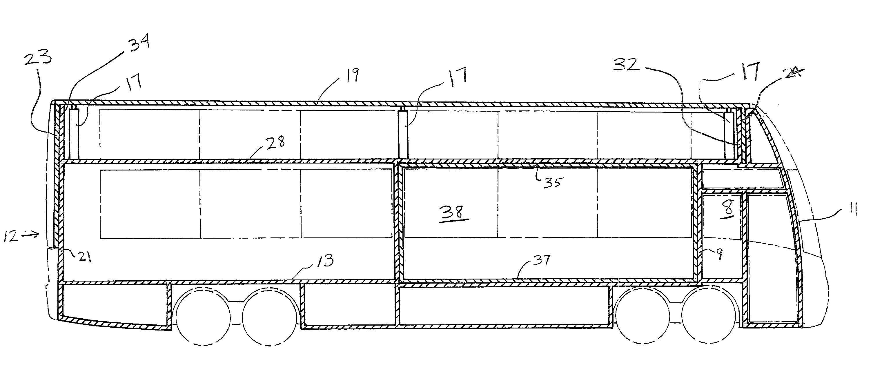
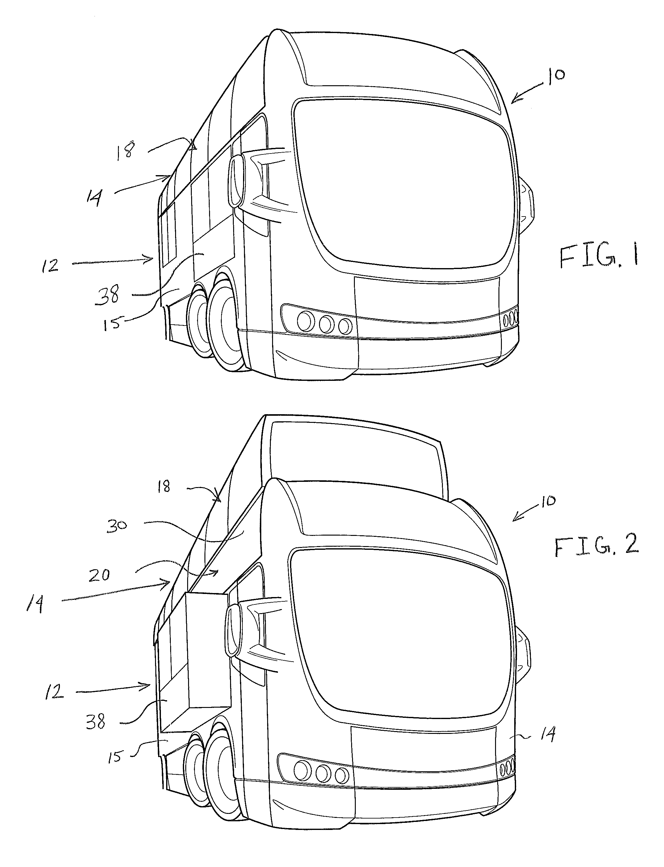
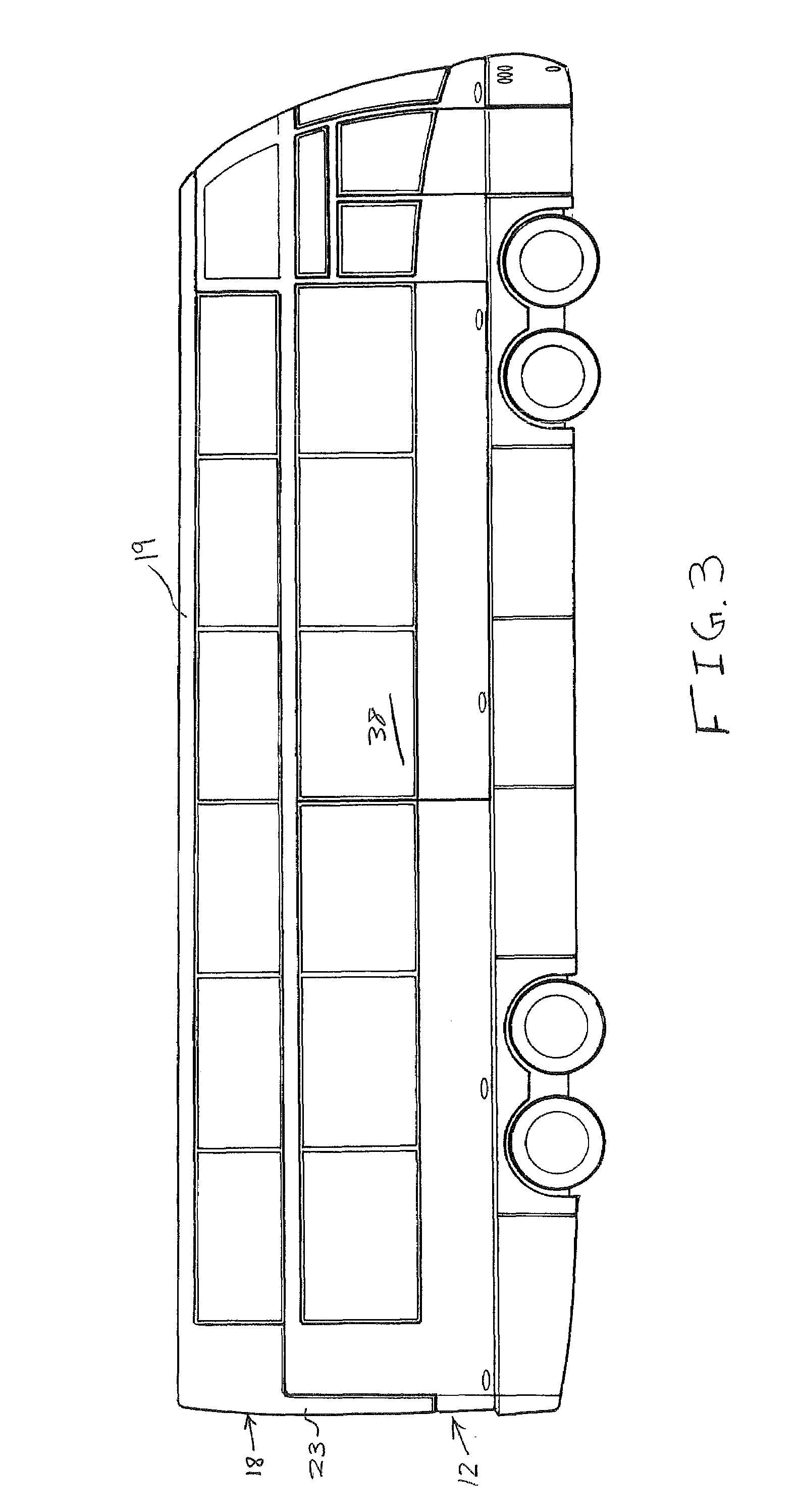
[0055]In a first embodiment, as shown in FIGS. 1-12, the side walls 25 of the upper segment 18 are continuous and do not accommodate extendable rooms. The side walls 15 of the lower body portion 12 in the first embodiment accommodate extendable rooms 38. The extendable rooms 38 each have a roof 35 and a floor 37 that slide within the lower body portion. The upper segment 18 and second floor 28 define an upper living area 41. FIGS. 1, 7, 8, and 11 show the upper segment 18 in its fully lowered position. The upper segment 18 overlaps the lower segment 20. The upper segment 18 is designed to be flush with the side wall 15 of the lower body portion 12 in its lowered position, which provides a streamlined surface. FIG. 11 shows in detail how actuators are mounted in the first embodiment to raise the upper segment 18, and how actuators are mounted to extend the rooms 38. The two types of actuators shown in FIGS. 8, 10, 11, and 12 are screw drives 60 and hydraulic cylinders 40, but could b...

second embodiment

[0058]In a second embodiment, as shown in FIGS. 13-24, the sidewalls 25 of the upper segment 18 contain upper extendable rooms 42. In this embodiment, the upper segment 18, extendable rooms 42 and second floor 28 define an upper living area 41. The upper extendable rooms 42 are slidably received in the upper body portion 14. The upper extendable rooms 42 have upper end walls 44 and lower end walls 46 that are in an overlapping, side by side relationship when the upper extendable rooms 42 are in their retracted positions, as shown in FIGS. 16 and 20. The lower end walls 46 are joined to floors 43 that slide over the second floor 28. The upper end walls 44 are joined to roofs 45 of the extendable rooms 42 that slide within the upper segment 18. Side walls 47 complete rooms 42. When the upper segment 18 is in its lowered position and the upper extendable rooms 42 are retracted, the walls 44 of the rooms 42 are flush with the side walls 15 of the lower body portion 12. The roofs 45 and ...

third embodiment

[0059]In a third embodiment, as shown in FIGS. 25-36, the sidewalls 25, 15 of the upper segment 18 and lower body portion 12 contain extendable rooms. The upper extendable rooms 42 and lower extendable rooms 38 are coordinated to extend simultaneously. As in the second embodiment, the upper extendable rooms 42 have an upper end wall 44 and a lower end wall 46 that are in an overlapping, side by side relationship when the upper extendable rooms 42 are in their retracted position, as shown in FIGS. 28 and 32. The lower end wall 46 of the upper extendable room 42 also forms a part of the wall 51 of the lower extendable room 38. A floor 53 of the upper extendable room 42 is attached where the lower end wall 46 and end wall 51 meet. The floor 53 of the upper extendable room 42 slides over the second floor 28. This is best shown in FIG. 34. When the upper segment 18 is in its lowered position, the upper extendable rooms 42 are in their retracted positions, and the lower extendable rooms 3...


PUM


Abstract

This invention relates to an expandable motor home. The motor home of this invention has a lower body portion having a first floor, a front wall, a back wall and a pair of opposite side walls. The motor home also has an upper body portion having a movable upper segment and a lower segment that is connected to the lower body portion. The lower segment has a front wall, a back wall and a pair of opposite side walls. The upper segment has a front wall, a back wall, a pair of opposite side walls, and a roof. The upper segment is movable relative to the lower segment such that the upper segment has a raised and lowered position relative to the lower body portion. The motor home may have extendable rooms in the upper segment and lower segment defining separate living areas.

Description

BACKGROUND OF THE INVENTION[0001]The interior space of a motor home is limited by size restrictions on vehicles which use public roads. In the past to provide more interior room expandable sides were used to widen the motor home when it was parked. During travel down public roads the sides are retracted to meet size limits for use on public roads. The interior space of a motor home could be nearly doubled if a second story could be affixed to the top of commonly available motor homes. A fixed second story is not a viable option for traveling due to size restrictions and limited vehicle height available due to bridges.SUMMARY OF THE INVENTION[0002]This invention relates to an expandable motor home. The motor home of this invention has a lower body portion having a first floor, a front wall, a back wall and a pair of opposite side walls. The motor home also has an upper body portion that is disposed over the lower body portion. The body portion has an upper segment and a lower segment...

Claims


Application Information

Patent Timeline
IPC IPC(8): B60P3/34
CPCB60P3/34
Inventor LUDWICK, ERIC
Owner LUDWICK ERIC
Why Eureka
Try Eureka