Pneumatic tire with tread having inclination grooves

a technology of pneumatic tires and grooves, which is applied in the field of pneumatic tires to achieve the effects of improving dry performance, enhancing stiffness, and raising driving stability during running on half-dried road surfaces

Inactive Publication Date: 2010-01-19
THE YOKOHAMA RUBBER CO LTD
View PDF19 Cites 0 Cited by
  • Summary
  • Abstract
  • Description
  • Claims
  • Application Information

AI Technical Summary

Benefits of technology

[0004]An object of the present invention is to provide a pneumatic tire capable of improving dry performance on a half dried road surface while maintaining high wet performance.
[0006]According to the present invention mentioned above, by narrowing the widths of the first main groove portions between the first blocks, the first blocks are larger in the widthwise direction, enabling stiffness thereof to be enhanced. Therefore, driving stability during running on a half dried road surface can be raised, enabling improvement of dry performance on a half dried road surface.
[0007]On the other hand, by disposing the right and left second inclination grooves at symmetrical positions, water can be expelled evenly sideways during running on a wet road surface. Therefore, the tire has a drainage effect higher than one having second inclination grooves offset in the circumferential direction of the tire. As a result, the arrangement of the second inclination grooves compensates for a decrease in drainage characteristics arising from narrowing of the widths of the first main groove portions, which can suppress reduction of drainage characteristics. Accordingly, wet performance as high as that of the prior art can be obtained.

Problems solved by technology

In this case, the above pneumatic tire providing high wet performance by the main groove and inclination grooves must degrade dry performance (driving stability) on the half dried road surface sections which conflicts with wet performance, requiring improvement thereof.

Method used


Image

  • Pneumatic tire with tread having inclination grooves
  • Pneumatic tire with tread having inclination grooves
  • Pneumatic tire with tread having inclination grooves

Examples


example

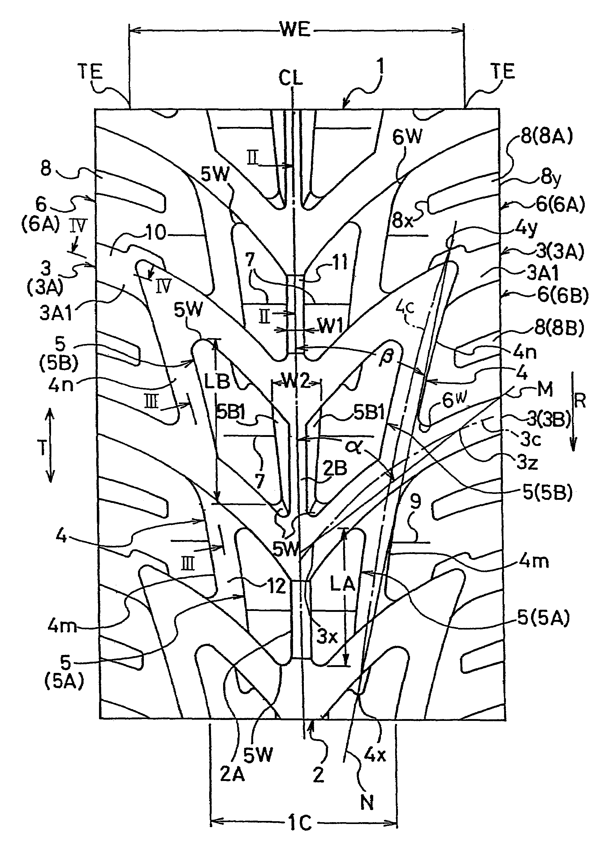
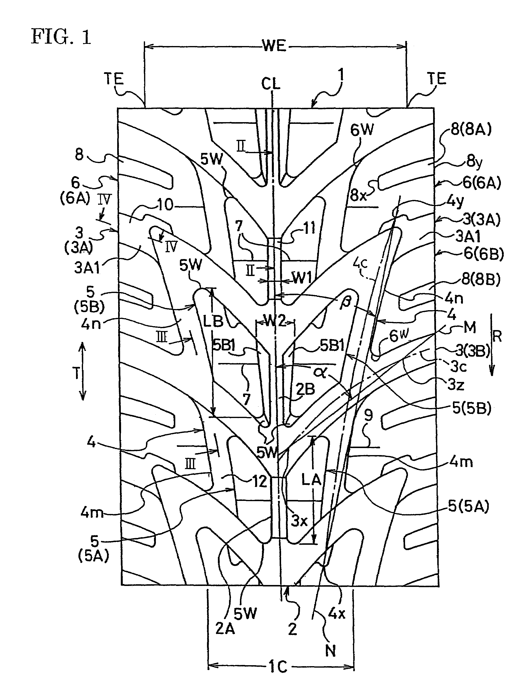
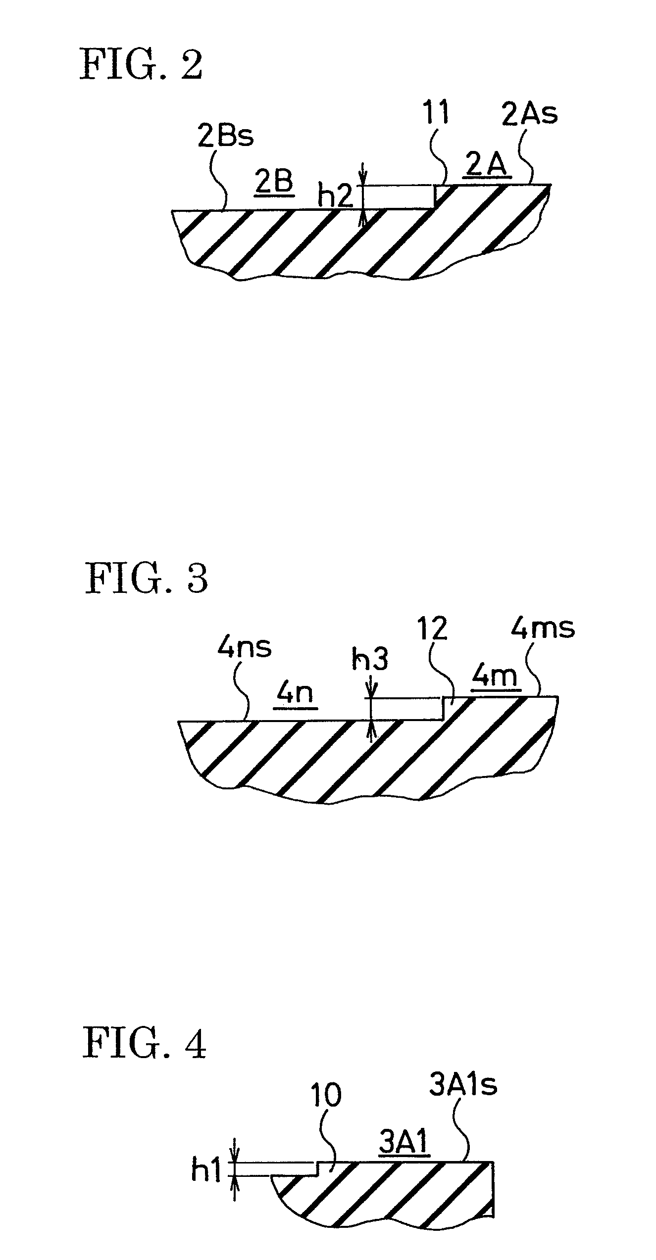
[0038]Prepared respectively were test tires according to the present invention tires 1 and 2 (present examples 1 and 2) and control tire (control example), each used for a front tire having a tire size of 4.5×10.0-5, each used for a rear tire having a tire size of 6.0×11.0-5, the present invention tire 1 having a structure shown in FIG. 1, the present invention tire 2 having the same structure as the present invention tire 1 except that there was no bottom-raising portion on the bottoms of the main groove, first inclination grooves and second inclination grooves, the control tire having the same structure as the present invention tire 2 except that the right and left second inclination grooves were disposed in positions offset in the circumferential direction of the tire and the main groove was constant in width.

[0039]In each of the present invention tires 1 and 2, the ratio W2 / W1 of the maximum width W2 of each second main groove portion to the minimum width W1 of each first main g...


PUM


Abstract

A pneumatic tire having a rotation direction specified in one direction. The tread surface has a main groove extending on the equatorial plane of the tire, right and left first inclination grooves extending in an inclined manner from the main groove toward the reverse rotation direction of the tire, and right and left second inclination grooves disposed on the opposite sides of the main groove. The right and left second inclination grooves are disposed at symmetrical positions with respect to the equatorial plane of the tire. Blocks are formed on the opposite sides of the main groove by the main groove, right and left first inclination grooves and right and left second inclination grooves. The blocks include right and left first blocks defined by tire rotation direction side portions of the second inclination grooves, main groove and first inclination grooves, and right and left second blocks defined by tire reverse rotation direction side portions of the second inclination grooves, main groove and first inclination grooves. First main groove portions between the right and left first blocks are less in width than second main groove portions between the right and left second blocks.

Description

BACKGROUND OF THE INVENTION[0001]The present invention relates to pneumatic tires, and more particularly, to a pneumatic tire which can improve dry performance on a half dried road surface while maintaining high wet performance.[0002]As one of pneumatic tires preferably used for racing cart tires which require high drainage characteristics when running straight and cornering on a rainy day, there has conventionally been known a pneumatic tire having a tread pattern in which a main groove extending in the circumferential direction of the tire is provided on the equatorial plane of the tire and two types of inclination grooves are adequately disposed on the opposite sides of the main groove (see Japanese Patent Application Kokai Publication 2003-175705, for example).[0003]A racing course for the carts includes half dried road surface sections having wet road surface conditions without water, and wet road surface sections having water thereon when running on a rainy day. When the carts...

Claims


Application Information

Patent Timeline
Patent Type & Authority Patents(United States)
IPC IPC(8): B60C11/11B60C11/12B60C11/13
CPCB60C11/0302B60C11/0316B60C11/1369Y10S152/03B60C2011/0374
Inventor SEKOGUCHI, MASAHARUMORI, SHINICHI
Owner THE YOKOHAMA RUBBER CO LTD
Why Eureka
Try Eureka