
Industrial truck

a technology for industrial trucks and cabs, applied in the field of industrial trucks, can solve the problem of not being able to form a disruptive lateral contour between the load and the cab for the operator in the cab

Active Publication Date: 2010-01-19
JUNGHEINRICH AG
View PDF38 Cites 5 Cited by
  • Summary
  • Abstract
  • Description
  • Claims
  • Application Information

AI Technical Summary

Benefits of technology

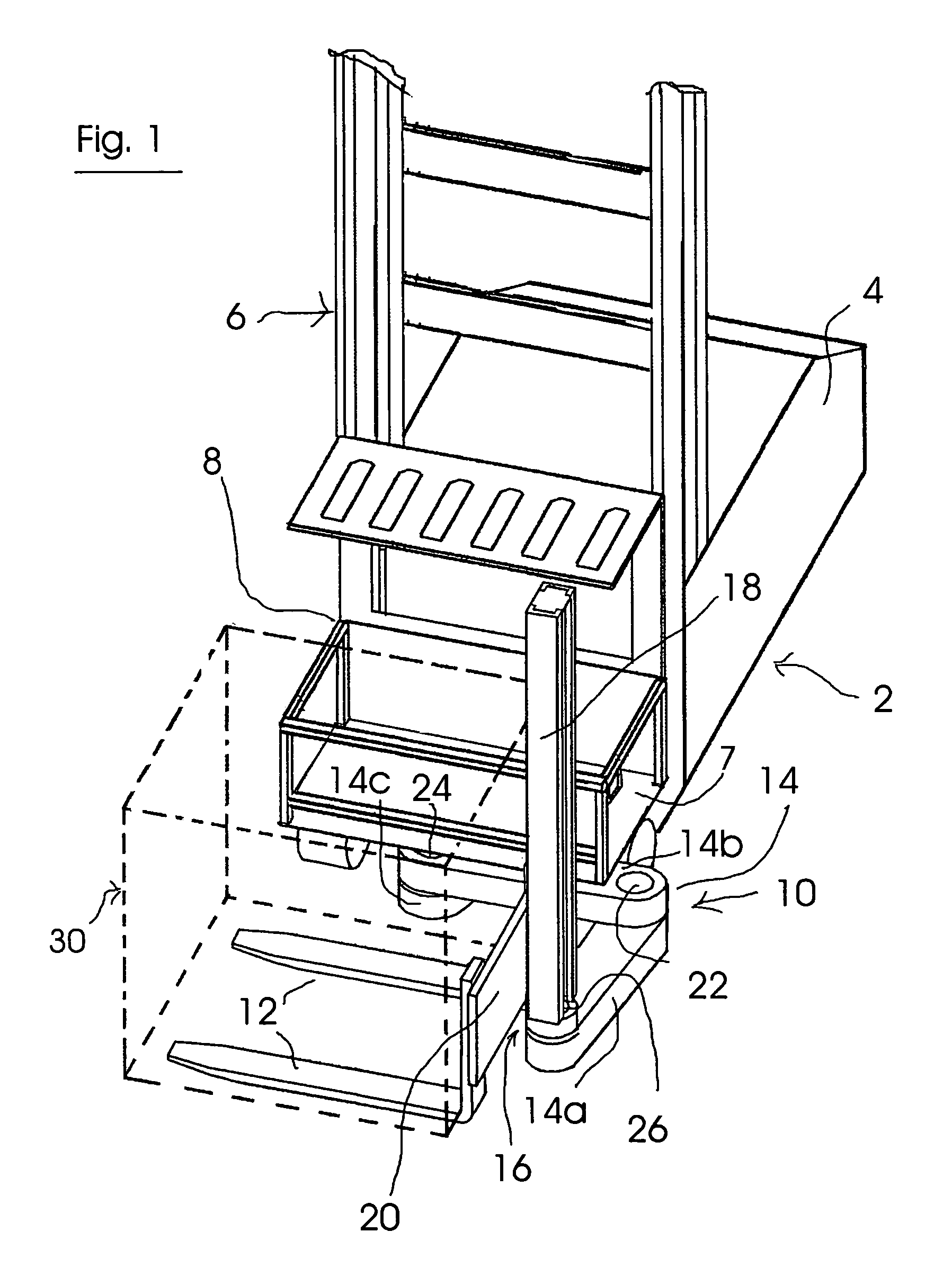
[0006]In preferred exemplary embodiments, the entire articulated arm extends at the height level beneath the driver's cab or at the height level above the driver's cab, with the result that it cannot form a disruptive lateral contour between the load and the cab for an operator in the cab.
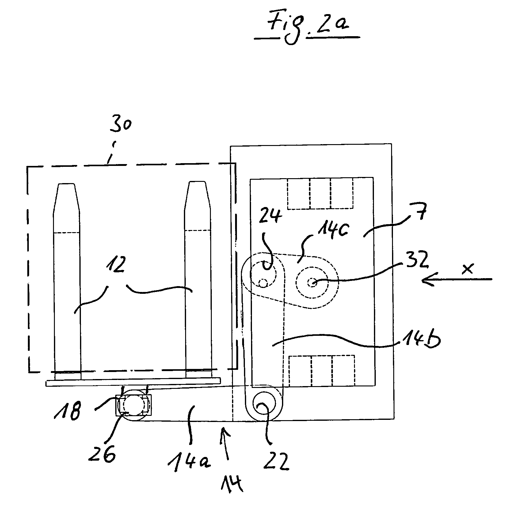
[0009]In accordance with one preferred embodiment, the articulated arm is articulated on the lifting device such that it can be pivoted about a normally vertical pivot axis by means of a main pivot bearing arrangement, with the result that it can carry out pivoting movements in the horizontal plane of its respective lifting position. The pivoting movements of the articulated arm elements take place in a controlled and coordinated manner by means of a control device in order, for example, to implement essentially straight displacement movements of the load-receiving means, for example of a load-bearing fork. In this case, in particular uniform and gentle movement sequences can be achieved. One advantage of such an industrial truck is the fact that the multiple-element articulated arm enables the load-receiving means to have a greater reach when it is moved in relation to the mobile base, it being possible for the load-receiving means to be positioned, moreover, in a more flexible manner, owing to the multiple-element articulated arm being pivoted in an appropriate manner, than is the case with order picker trucks and trilateral stackers of the conventional type.
[0012]In order to avoid a complicated design, the articulated arm has preferably merely two articulated arm elements. In this case, provision may be made for at least one of the articulated arm elements to be arranged such that it can be longitudinally displaced in relation to the pivot bearing, which holds it such that it can pivot, on said pivot bearing, or to be capable of being telescoped. The articulated arm element arranged on the lifting device directly by means of the main pivot bearing arrangement is preferably guided such that it can be longitudinally displaced in relation to the main pivot bearing arrangement, with the result that it can carry out mutually overriding movements of pivoting about the pivot axis and displacement transverse with respect to the pivot axis of the main pivot bearing arrangement. This makes it possible to carry out mutually overriding movements of pivoting and displacement in order to produce a specific, in particular linear movement sequence for the load-receiving means.
[0015]If necessary, it is also possible for the pivoting arm to move the load-receiving means obliquely with respect to the straight-on direction of travel of the mobile base or longitudinally curved tracks. These examples already show that the multiple-element articulated arm makes it possible to manipulate the load-receiving means and a load located thereon in a very flexible manner.

Problems solved by technology

In preferred exemplary embodiments, the entire articulated arm extends at the height level beneath the driver's cab or at the height level above the driver's cab, with the result that it cannot form a disruptive lateral contour between the load and the cab for an operator in the cab.

Method used


Image

  • Industrial truck
  • Industrial truck
  • Industrial truck

Examples


Embodiment Construction

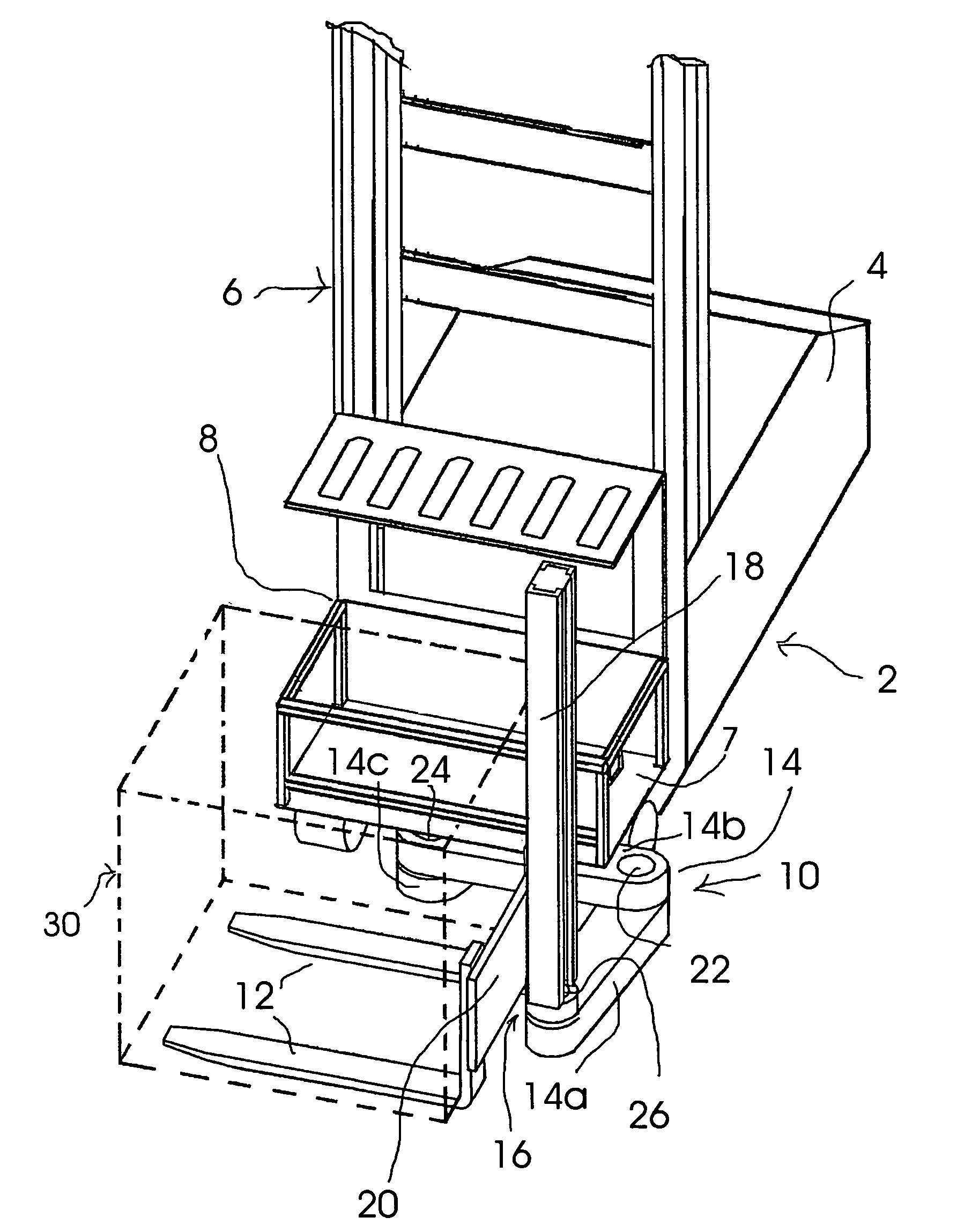
[0031]FIG. 1 shows a perspective illustration with a view of the front region of an industrial truck which can be used as a high-reach stacker. The industrial truck has a base vehicle 2, which has an essentially conventional design and has an electric motor drive.

[0032]Batteries for supplying the vehicle with electrical power, hydraulic assemblies, parts of the steering device, electronic or electrical components etc. are located beneath the hood 4 in the rear region of the vehicle 2. A mast 6 (illustrated partially) is provided on the base vehicle 2 and, in a known manner, has a rigid lower mast element and an upper mast element which can be displaced vertically and telescopically on said rigid lower mast element, a platform with a driver's cab 8 being guided on said upper mast element such that it can be moved vertically. The lifting drive in this example is hydraulic, as is conventional in the case of stacker vehicles of the type in question here.

[0033]The add-on device 10 of the...


PUM


Abstract

An industrial truck, in particular a stacker vehicle, having a mobile base, a cab, which can be moved in relation to the mobile base, for an operator, a load-receiver and a device, which is arranged on the mobile base, for moving the load-receiver in relation to the mobile base, wherein the device for moving the load-receiver has a multiple-element articulated arm as a support, which can be moved in a controllable manner, for the load-receiver, and wherein the articulated arm, starting from a base-side articulation point beneath the cab or starting from a base-side articulation point above the cab, extends to the load-receiver, the elements of the articulated arm being connected to one another by pivot bearings—and being capable of being moved in relation to one another in order to manipulate the load-receiver.

Description

BACKGROUND OF THE INVENTION[0001]The invention relates to an industrial truck, in particular a stacker vehicle, having a mobile base, a cab, which can be moved in relation to the mobile base, for an operator, a load-receiving means and a device, which is arranged on the mobile base, for moving the load-receiving means in relation to the mobile base.[0002]Industrial trucks of the abovementioned type have been implemented in various embodiments, for example as high-reach stackers, order picker trucks or trilateral stackers. A current design for such a conventional order picker truck or trilateral stacker comprises a mobile base (base vehicle) having a mast, which is provided for the purpose of lifting and lowering a platform with a driver's cab. An add-on device, which comprises a so-called pivot-and-reach device for a load-receiving means, is fixed to the front of the driver's cab. The pivot-and-reach device has a load-receiving means holder, which can be moved vertically on an addit...

Claims


Application Information

Patent Timeline
IPC IPC(8): B66F9/14
CPCB66F9/07545B66F9/10
Inventor SCHOTTKE, CARSTEN
Owner JUNGHEINRICH AG
Learn More