
Tool for chipless production or finishing of a thread, method for producing the tool and method for producing a thread

a technology for chipless production or reworking, a production method and a production method, which are applied in the manufacture of tools, thread cutting machines, thread cutting apparatuses, etc., can solve the problems of obstructing the alignment of the probe to the surface, obstructing the accuracy of the profile measurement with a known stylus instrument, and achieving less time expenditure and high accuracy.

Active Publication Date: 2021-05-13
EMUGE WERK RICHARD GLIMPEL & FAB FUR PRAZISIONSWERKZEUGE
View PDF0 Cites 1 Cited by
  • Summary
  • Abstract
  • Description
  • Claims
  • Application Information

AI Technical Summary

Benefits of technology

The invention is a tool for non-cutting production or finishing of a thread, especially a ball thread, in a workpiece. The tool has a rotating shaping region with multiple pressing lobes that create the thread by pressing into the surface of the workpiece. The pressing lobes are designed with a rounded shape to improve surface access during use. The method and tool can produce threads with high accuracy in less time.

Problems solved by technology

The well-known procedure is time-consuming.
In order to use a stylus instrument, the line to be measured must have certain characteristics, in particular, protruding areas of the surface may obstruct the alignment of the probe to the surface.
Such a profile cannot be measured with sufficient accuracy with a known stylus instrument.
In particular, the profile along the pressing lobes cannot be measured with sufficient accuracy with known, especially polygonally formed, thread grooves.

Method used


Image

  • Tool for chipless production or finishing of a thread, method for producing the tool and method for producing a thread
  • Tool for chipless production or finishing of a thread, method for producing the tool and method for producing a thread
  • Tool for chipless production or finishing of a thread, method for producing the tool and method for producing a thread

Examples


Embodiment Construction

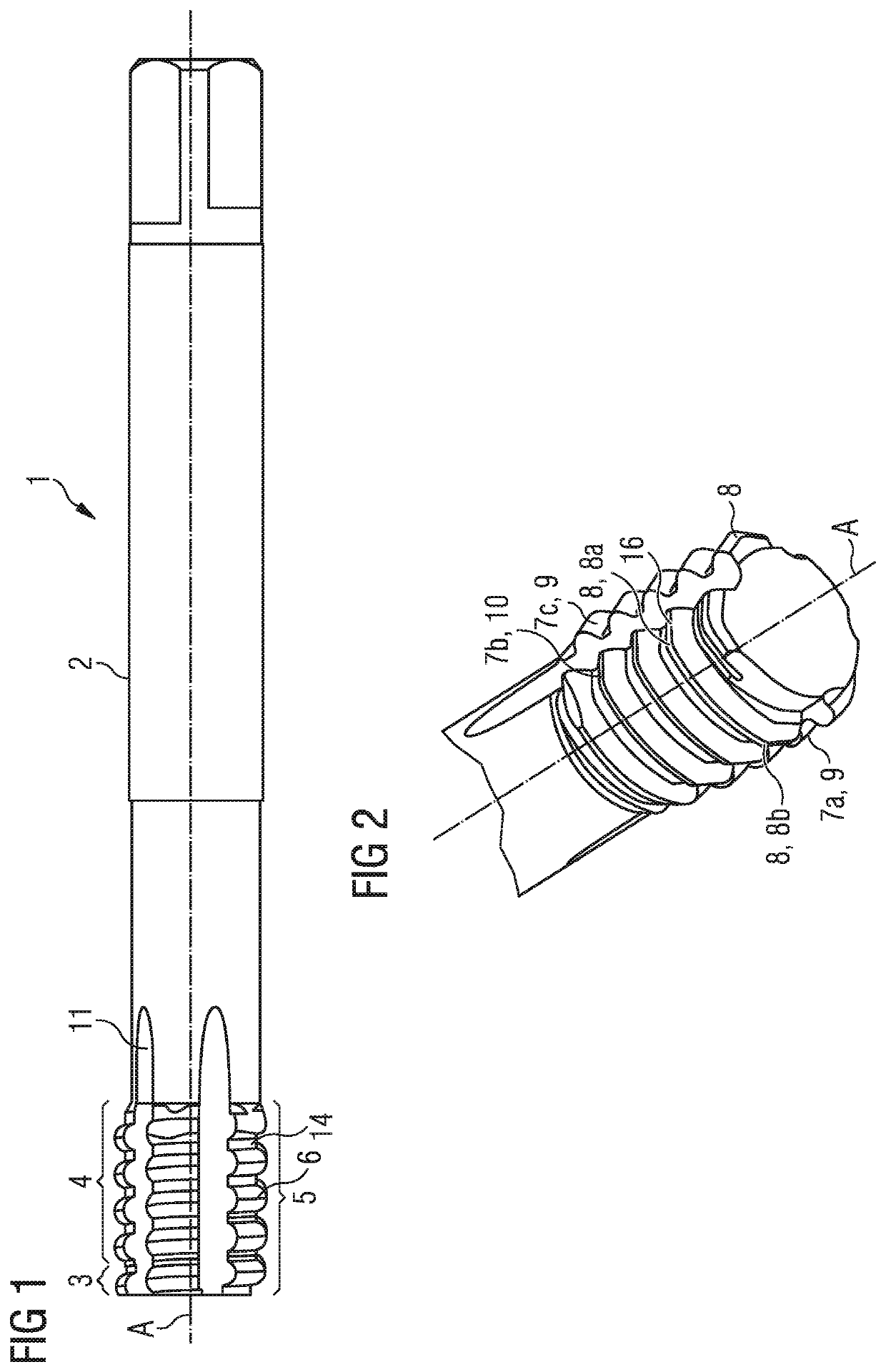
[0036]The cold forming tab 1 in FIG. 1 has a shank 2 and a forming region 5. The shank is cylindrical at least in sections and has a square profile at an end facing away from forming region 5, which is suitable for mounting in a chuck of a thread generating device. The cold forming tab has a tool axis A, which is the axis of rotation.

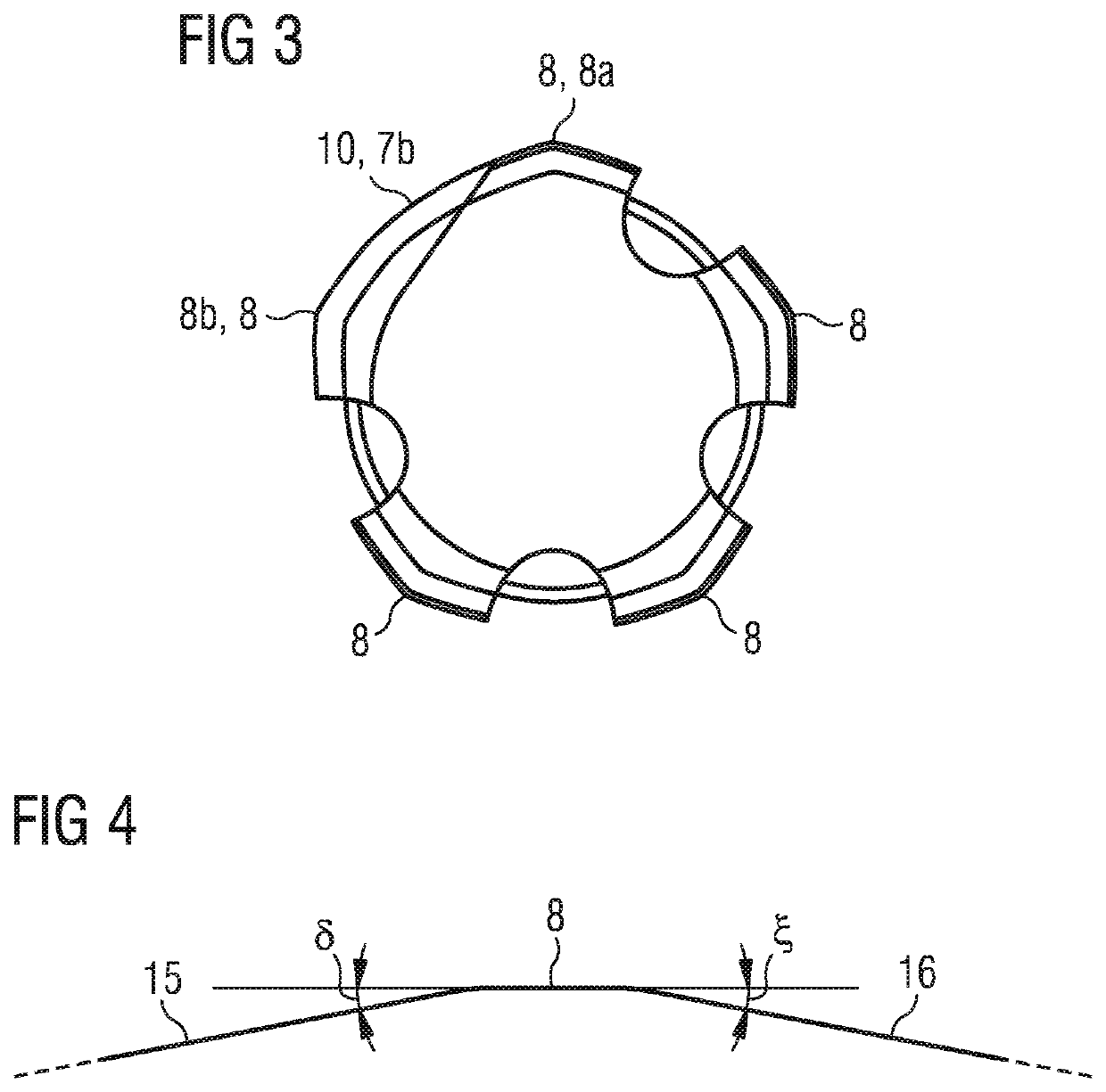
[0037]The shaping region 5 is divided into a forming region 3 facing a tool tip and a calibrating region 4. In shaping region 5, pressing lobes 7 are arranged in pressing ridges 9, 10. The pressing ridges 9, 10 are straight pressing ridges. The pressing lobes 7 lie on a spiral forming curve 6, which has a helix angle α. In the calibration region 4, the pressing lobes 7 have a greater radial height than in the forming region 3. A lubrication groove 11 is arranged between two adjacent pressing ridges 9, 10. The pressing ridges 9, 10 and the lubrication grooves 11 run parallel to a tool axis A.

[0038]Adjacent pressing lobes 7 in a pressing ridge 9, 10 do no...


PUM

PropertyMeasurementUnit
Angleaaaaaaaaaa
Lengthaaaaaaaaaa
Shapeaaaaaaaaaa

Abstract

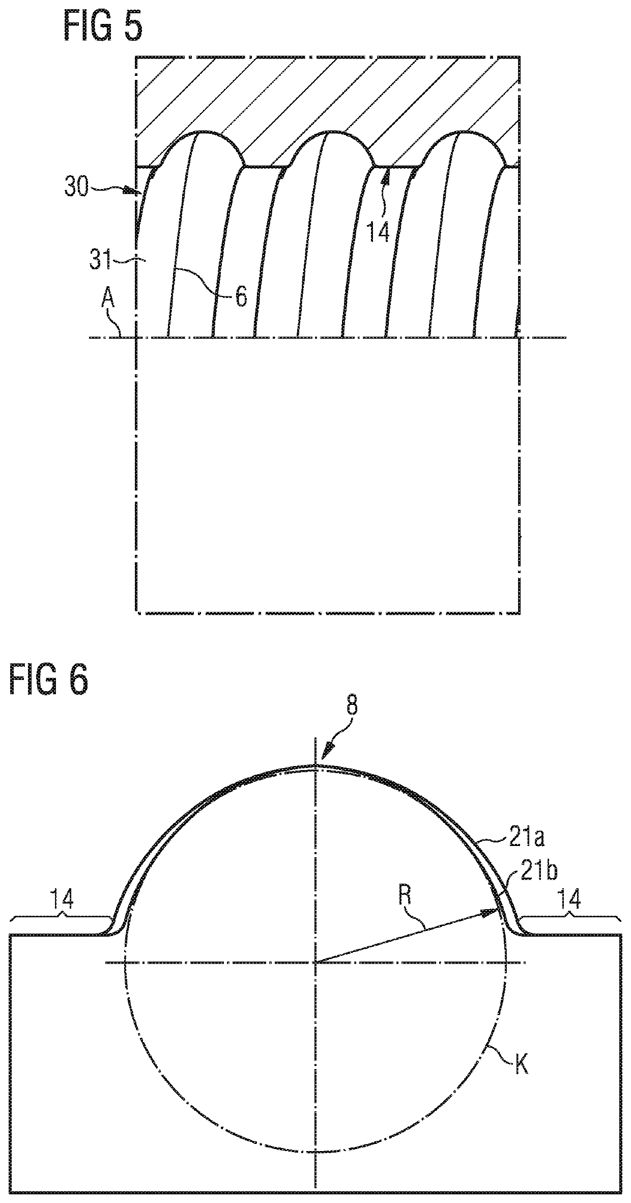
A tool for the chipless production of a thread in a workpiece comprises at least one shaping region which can be rotated about a tool axis (A) for the chipless production or finishing of the thread. The shaping region comprises a plurality of pressing lobes projecting radially outwardly from the tool axis (A) for producing the thread by pressing the pressing lobes into the workpiece surface. The pressing lobes are successively arranged along a forming curve which substantially spirals around the tool axis (A), and the pitch of the forming curve essentially corresponds to the pitch of the thread to be produced or reworked. The forming curve has a helix angle (a), and a profile of at least one pressing lobe is designed in such a way that a thread produced in an axial section containing the tool axis is at least in sections round-arched or ogival.

Description

CROSS-REFERENCE TO RELATED APPLICATIONS[0001]The present invention claims the benefit of priority to German Patent Application No. DE 10 2019 130 009.6, filed Nov. 7, 2019, the entire content of which is incorporated herein by reference.BACKGROUND OF THE INVENTION1. The Field of the Invention[0002]The invention relates to a tool for chipless production or reworking of a thread, a method for producing the tool and a method for producing a thread.2. Background and Relevant Art[0003]A ball screw drive is a screw drive with balls inserted between the screw and nut. When turning between screw and nut, the balls roll in a corresponding ball thread (or: ball thread groove). Such a ball thread is conventionally produced with the help of mounted points. The well-known procedure is time-consuming. Such a ball thread must have a high accuracy. A high accuracy can only be achieved if the manufactured thread can also be measured.[0004]For measuring such a thread, stylus instruments are known fro...

Claims


Application Information

Patent Timeline
IPC IPC(8): B23G5/06B23G1/04
CPCB23G5/06B23G1/04B23G1/16B23P15/52B23P15/48B23G7/02
Inventor HECHTLE, DIETMARÜBLER, MARKOFENZEL, JÜRGEN
Owner EMUGE WERK RICHARD GLIMPEL & FAB FUR PRAZISIONSWERKZEUGE
Learn More