Patterned coated dichroic filter

a dichroic filter and coating technology, applied in the field of patterned coating dichroic filters, can solve the problems of optical arts that have failed to produce thin filters with well-defined edges, and the art of microlithography has been limited to the field of microelectronics, so as to facilitate the formation of the remaining layers, improve resolution, and reduce the defect of display devices

Active Publication Date: 2010-01-19
OCEAN OPTICS
View PDF3 Cites 44 Cited by
  • Summary
  • Abstract
  • Description
  • Claims
  • Application Information

AI Technical Summary

Problems solved by technology

As mentioned earlier, the optical arts have failed to produce thin filters having well -defined edges, and the art of microlithography has been limited to the field of microelectronics.

Method used


Image

  • Patterned coated dichroic filter
  • Patterned coated dichroic filter
  • Patterned coated dichroic filter

Examples


Embodiment Construction

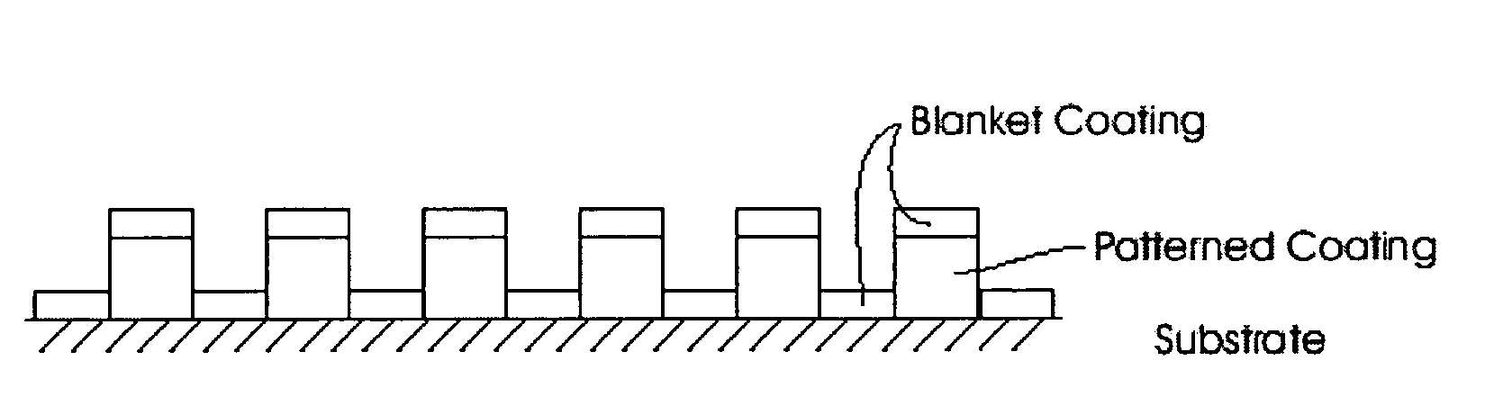
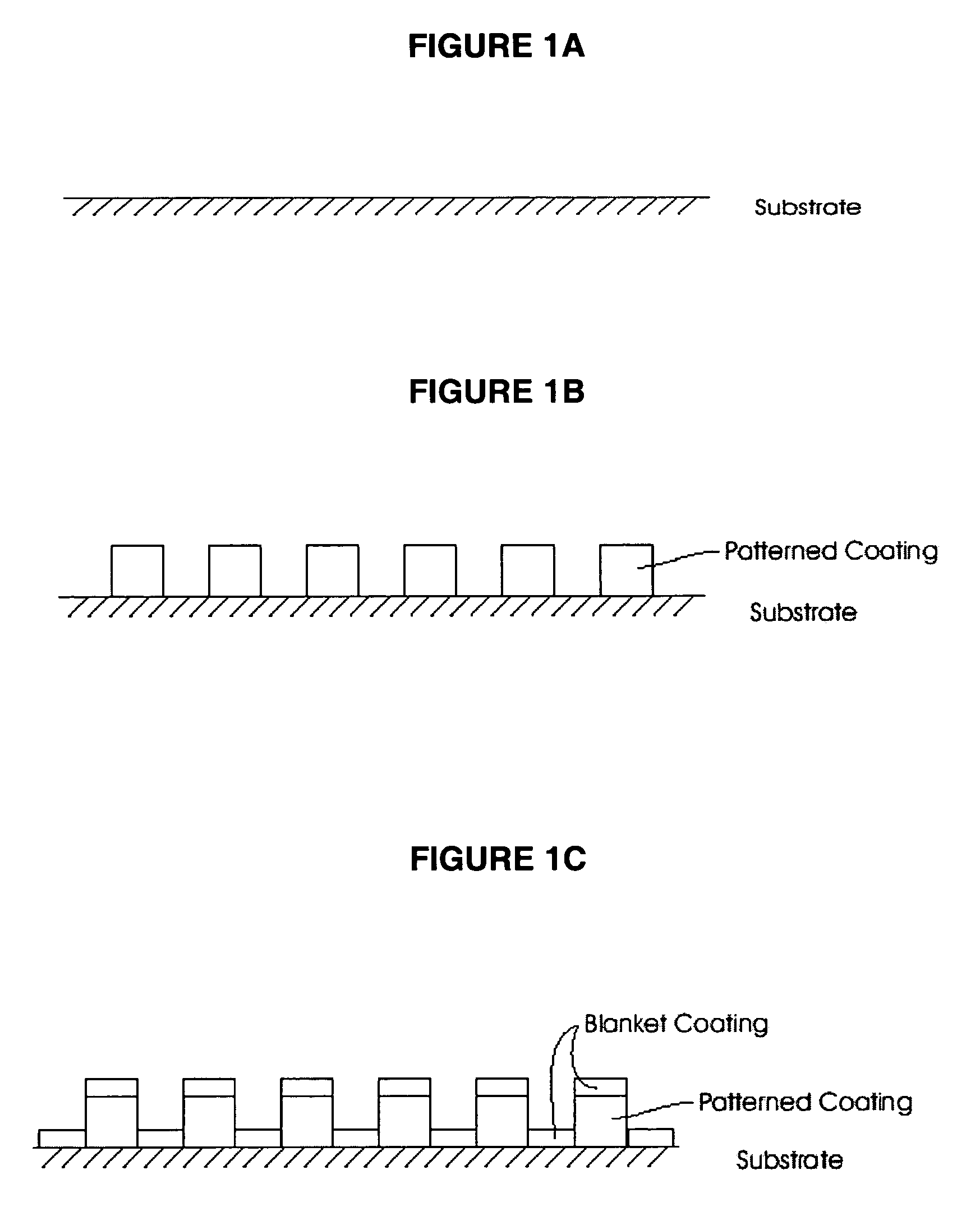
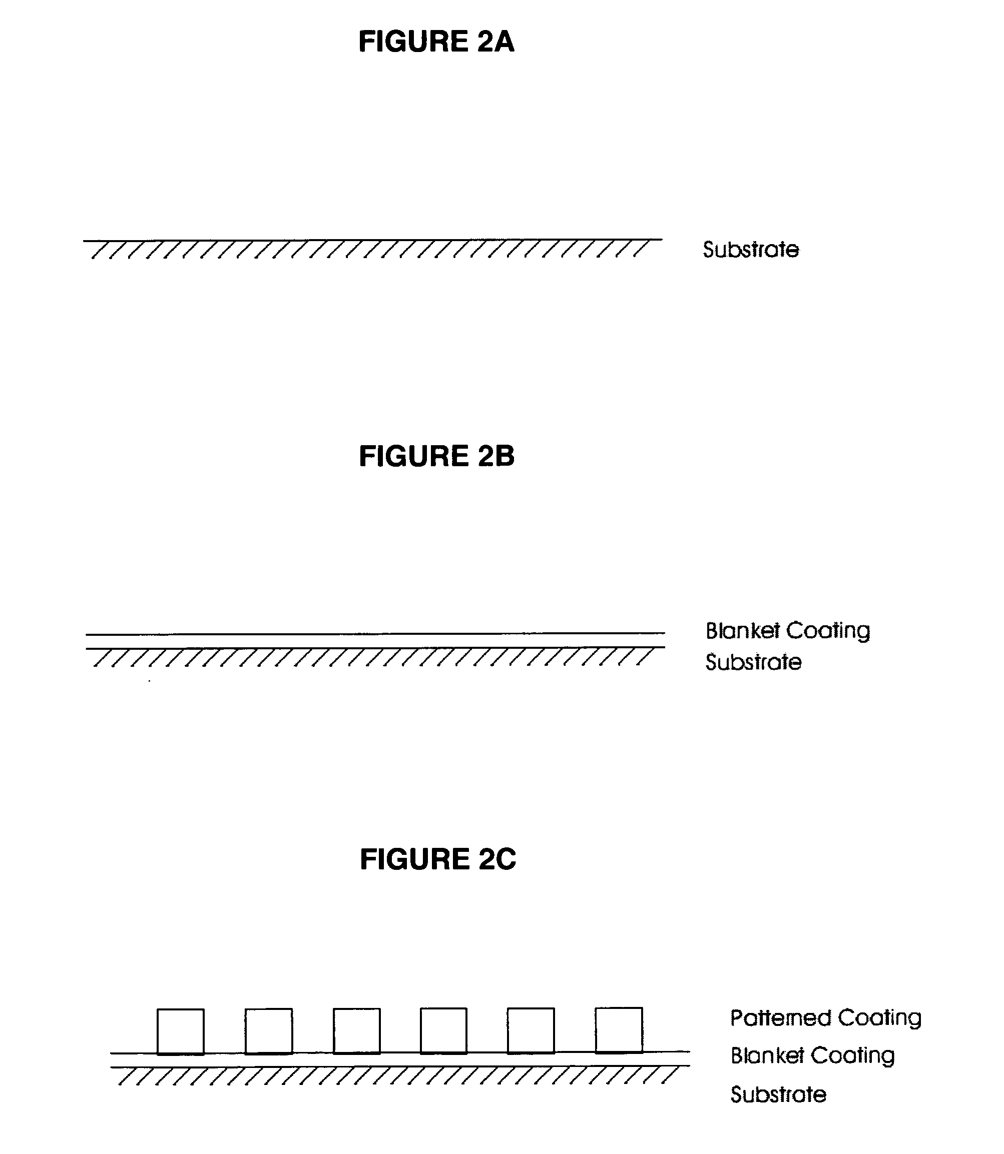
[0020]As shown in FIGS. 1a, 1b, and 1c the method and filter of the preferred embodiment begins with the application and patterning of a photosensitive material (not shown) on a substrate (1) as outlined in U.S. Pat. No. 5,711,889 but leaving off several dichroic layers of the patterned dichroic material (2) and replacing them with a blanket coating (3) such as an anti-reflective coating to complete the spectral characteristics desired. The steps as described in U.S. Pat. No. 5,711,899 are generally patterning photoresist on a substrate and masking pre-selected areas of said substrate via proximity, contact printing or other masking techniques well known in the art (1) and coating a dichroic material (2) in the desired pattern. In most cases, but not all, multiple alternating layers of SiO2 and Ta2O5 are applied while lifting off the photoresist to form the patterned dichroic material (2). Then the whole surface is coated with an anti-reflective blanket coating (3) which, when combi...


PUM

PropertyMeasurementUnit
thicknessaaaaaaaaaa
areasaaaaaaaaaa
color bandpassaaaaaaaaaa

Abstract

A combination patterned reflective dichroic filter and optical coating, and method of making the same, is disclosed by starting with a filter substrate, laying down a pattern of dichroic filter material, but stopping short of completing the layers required for the spectral characteristics of the filter. The spectral characteristics are completed by adding a blanket coating of a material such as an anti-reflective material. In an alternative embodiment the blanket coating can be applied prior to addition of the dichroic filter material.

Description

CROSS-REFERENCE TO RELATED APPLICATION[0001]The present application claims the benefit of previously filed pending Provisional Patent Application, Ser. No. 60 / 535,756, filed Jan. 12, 2004.FIELD OF THE INVENTION[0002]This invention relates, generally, to methods for making a patterned coated dichroic filter. More specifically a method for replacing several layers of the patterned dichroic materials with a blanket coating of anti-reflective or other optical coating that completes the spectral requirements of the patterned dichroics.BACKGROUND OF THE INVENTION[0003]Dichroic filters, also known as interference filters, are constructed by depositing one or more layers of metallic and / or dielectric films with precise thicknesses to produce filters which transmit certain wavelengths of light and reflect others. The colors of a dichroic filter can be predicted and manufactured to match spectral functions such as the CIE tristimulus curves s (e.g. the 1976 UCS standard chromaticity diagram),...

Claims


Application Information

Patent Timeline
Patent Type & Authority Patents(United States)
IPC IPC(8): G02B5/20G02B1/11
CPCG02B1/11G02B5/201
Inventor BUCHSBAUM, PHILIP E.LANE, JAMES D.
Owner OCEAN OPTICS
Why Eureka
Try Eureka