Reflective polarizer with polarization splitting microstructure

a technology of reflective polarizer and microstructure, which is applied in the field of reflective polarizer film, can solve the problems of high layer count, difficult to manufacture at low cost for a large area, and angular performance of the coating limit the useful function of the prismatic reflective polarizer b, so as to achieve a larger tolerance for incident angle and wavelength and be manufactured at a lower cost.

Inactive Publication Date: 2007-12-06
SKC HI TECH & MARKETING CO LTD CO REGISTRATION NO 161511 0225312
View PDF4 Cites 39 Cited by
  • Summary
  • Abstract
  • Description
  • Claims
  • Application Information

AI Technical Summary

Benefits of technology

[0011](c) a light-exit medium on the polarization-selective thin film optical coating that provides a smooth light-exit surface.
[0012]The invention also comprises a method of fabricating the polarizer and an LCD display containing the polarizer. The polarizer of the invention with the indicated inclination angle has a larger tolerance for incident angle and wavelength than other known prismatic reflective polarizers, and can be manufactured at lower cost.

Problems solved by technology

However, to date, such prismatic reflective polarizers have not been commercialized because of poor performance and high manufacturing cost.
Such a high layer count would be very challenging to manufacture at low cost for a large area.
Furthermore, as described in '634, the angular performance of the coating limits the useful function of the prismatic reflective polarizer 10 to an angular range of approximately ±10 degrees in air.
The limited angular performance is due, in large part, to the fact that light is incident on the thin film optical coating 18 at angle of approximately 45 degrees with respect to the surface normal.
As is well known in the art, polarizing optical film stacks are more difficult to design, and have a narrower performance range, for 45 degree incidence than at somewhat larger angles.
The prismatic reflective polarizers that have been previously disclosed have two significant challenges: 1) a severe angular and wavelength sensitivity, limiting the number of suitable applications, and 2) a large number alternating high and low refractive layers, leading to high manufacturing cost.
Increasing the layer count can diminish wavelength sensitivity, but this remedy increases manufacturing cost even further.

Method used


Image

  • Reflective polarizer with polarization splitting microstructure
  • Reflective polarizer with polarization splitting microstructure
  • Reflective polarizer with polarization splitting microstructure

Examples


Embodiment Construction

[0034]The present description is directed in particular to elements forming part of, or cooperating more directly with, apparatus in accordance with the invention. It is to be understood that elements not specifically shown or described may take various forms well known to those skilled in the art.

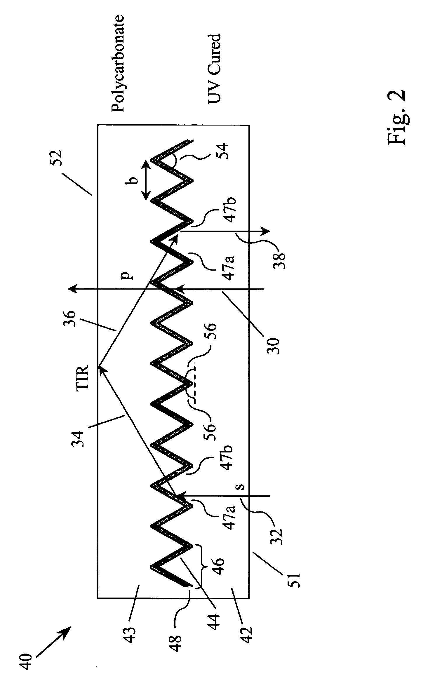
[0035]FIG. 2 illustrates the prismatic reflective polarizer 40 of the present invention, which can be designed to provide good performance simultaneously over the entire visible spectrum and over a wide range of incidence angles. In addition, the invention can be fabricated at relatively low cost. The prismatic reflective polarizer 40 has a light-entrance medium 42 with a light-entrance surface 51 and an opposing microstructured surface 44 that contains a series of prismatic structures 46. A thin film optical coating 48, with alternating thin film layers of high and low refractive index materials, is situated on the microstructured surface 44. In a preferred embodiment, the optical coating...


PUM

PropertyMeasurementUnit
inclination angleaaaaaaaaaa

Abstract

A reflective polarizer contains:(a) a light-entrance medium having a light-entrance surface and a microstructured surface with a series of prismatic structures, wherein first and second sidewalls of each prismatic structure have an inclination angle of more than 53 degrees with respect to the light-entrance surface;(b) a polarization-selective thin film optical coating on the series of prismatic structures, for transmitting a first polarization of light and reflecting a second polarization; and(c) a light-exit medium on the polarization-selective thin film optical coating that provides a smooth light-exit surface.

Description

CROSS REFERENCE TO RELATED APPLICATION[0001]This application claims priority of provisional application 60 / 810,885 filed on Jun. 5, 2006.FIELD OF THE INVENTION[0002]This invention relates to a reflective polarizer film that preferentially transmits one polarization of light and reflects the orthogonal polarization. More particularly, the invention relates to a reflective polarizer film that contains a prismatic interface microstructure with a polarization-dependent thin film optical coating. The invention is particularly useful for increasing the brightness and efficiency of LCD backlights.BACKGROUND OF THE INVENTION[0003]Reflective polarizers are widely used in liquid crystal displays (LCD) backlights to increase image brightness and light utilization efficiency. The reflective polarizers usually serve as pre-polarizers for recycling the polarization component that would be absorbed by the absorbing polarizers of the LCD. Current LCDs utilize primarily two types of reflective polar...

Claims


Application Information

Patent Timeline
Patent Type & Authority Applications(United States)
IPC IPC(8): G02F1/1335
CPCG02B5/045G02F1/13362G02B5/3066G02B5/30G02F1/1335
Inventor KOWARZ, MAREK W.GREENER, JEHUDAANDERSON, CHARLES C.
Owner SKC HI TECH & MARKETING CO LTD CO REGISTRATION NO 161511 0225312
Why Eureka
Try Eureka