
Pivot linkage including a non-contact, rotational angle measurement sensor for heavy machinery

a technology of rotating angle measurement and sensor, applied in the field of sensors, can solve the problem that the angle measurement sensor is an extremely long life angle measurement sensor, and achieve the effects of reducing the risk of damag

Inactive Publication Date: 2006-05-02
JOY MM DELAWARE INC
View PDF9 Cites 26 Cited by
  • Summary
  • Abstract
  • Description
  • Claims
  • Application Information

AI Technical Summary

Benefits of technology

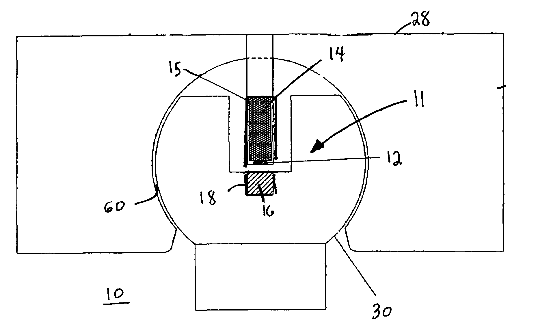
[0011]The angle measurement sensor of the pivot linkage uses the magnetoresistive effect in measuring the angle between rotating components. The angle measurement sensor includes one or more permanent magnets for producing a magnetic field and a magnetoresistive sensing circuit for detecting changes in the direction of the magnetic field in response to relative rotation between the two rotating components. The permanent magnets are incorporated into one member of the pivot linkage that is coupled to a rotating components of the machinery and the sensor and associated signal conditioning circuits are incorporated into another member of the pivot linkage that is coupled to the other moving component of the machinery. This system of angle measurement allows up to 0.5 inch gap between the magnetoresistive sensing circuit and the permanent magnets, without affecting the accuracy of the measurement.
[0013]The angle measurement sensor is a non-exposed, integral part of the mechanical joint linkage that couples together two moving parts, the rotational angle of which is to be measured. The angle measurement sensor and its associated electronics can be hermetically sealed and the housing of the angle measurement sensor can be made from non-corrosive metals. Thus, the angle measurement sensor can operate while immersed in grease, oil or water. Moreover, the non-contact angle measurement sensor has no moving parts or wear items. Consequently, the angle measurement sensor is an extremely long life angle measurement sensor.
[0014]In contrast to conventional angle measurement sensors, such as potentiometers that are susceptible to mechanical tolerances, the novel non-contact angle measurement sensor provided by the present invention allows a large degree of mechanical tolerance.
[0015]Moreover, typical carbon film, metal film and wire wound potentiometers used as sensors have a limited life time due to them being contact type angle measurement sensors. In contrast, the non-contact design angle measurement sensor provided by the present invention is a solid state device and has no wear parts and therefore has a much longer life.
[0017]The pivot linkage including the rotational angle measurement sensor is of a construction which is both durable and long lasting, and which will require little or no maintenance to be provided by the user throughout its operating lifetime. The pivot linkage including the angle measurement sensor of the present invention is of inexpensive construction to enhance its market appeal and to thereby afford it the broadest possible market. Finally, all of the aforesaid advantages and objectives are achieved without incurring any substantial relative disadvantage.

Problems solved by technology

Consequently, the angle measurement sensor is an extremely long life angle measurement sensor.

Method used


Image

  • Pivot linkage including a non-contact, rotational angle measurement sensor for heavy machinery
  • Pivot linkage including a non-contact, rotational angle measurement sensor for heavy machinery
  • Pivot linkage including a non-contact, rotational angle measurement sensor for heavy machinery

Examples


Embodiment Construction

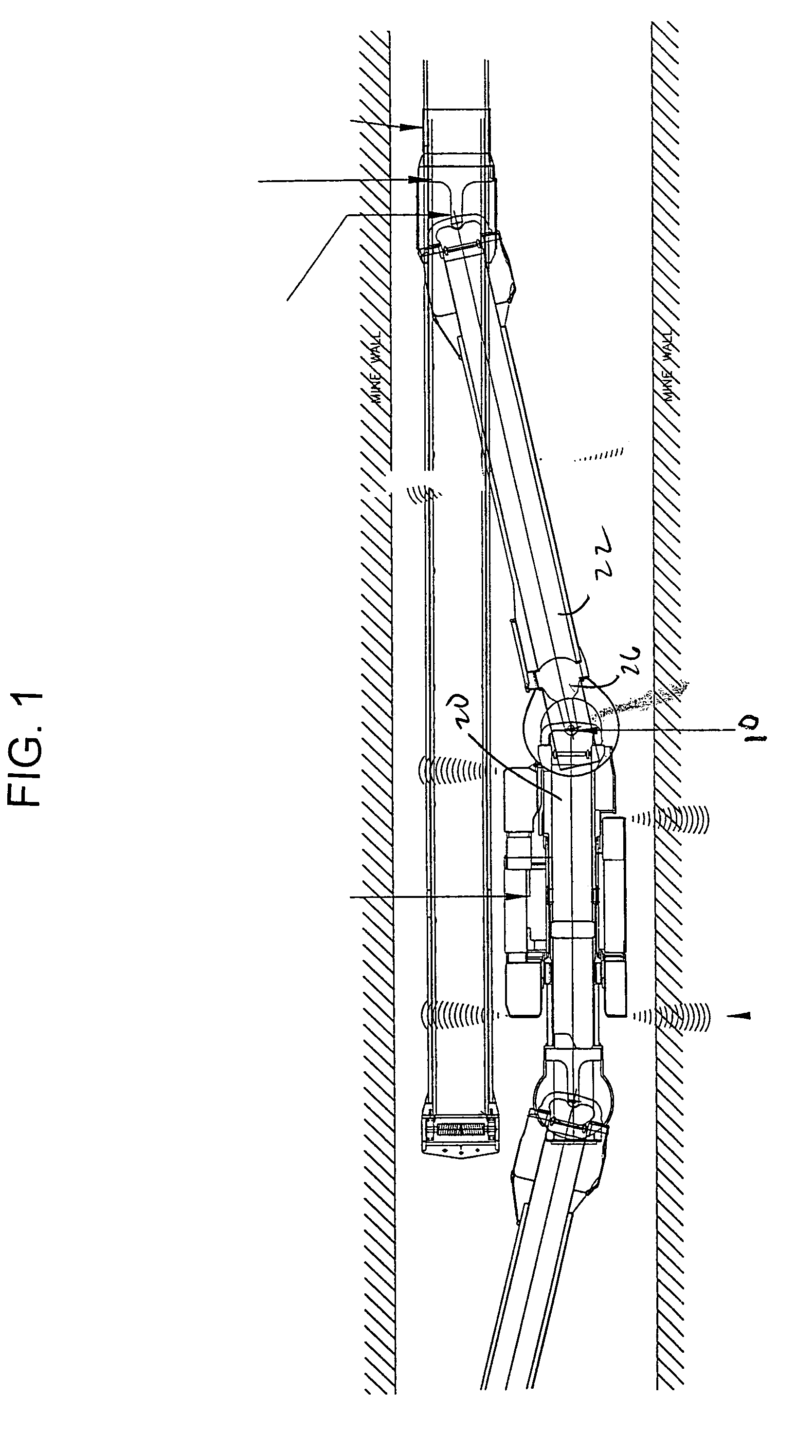
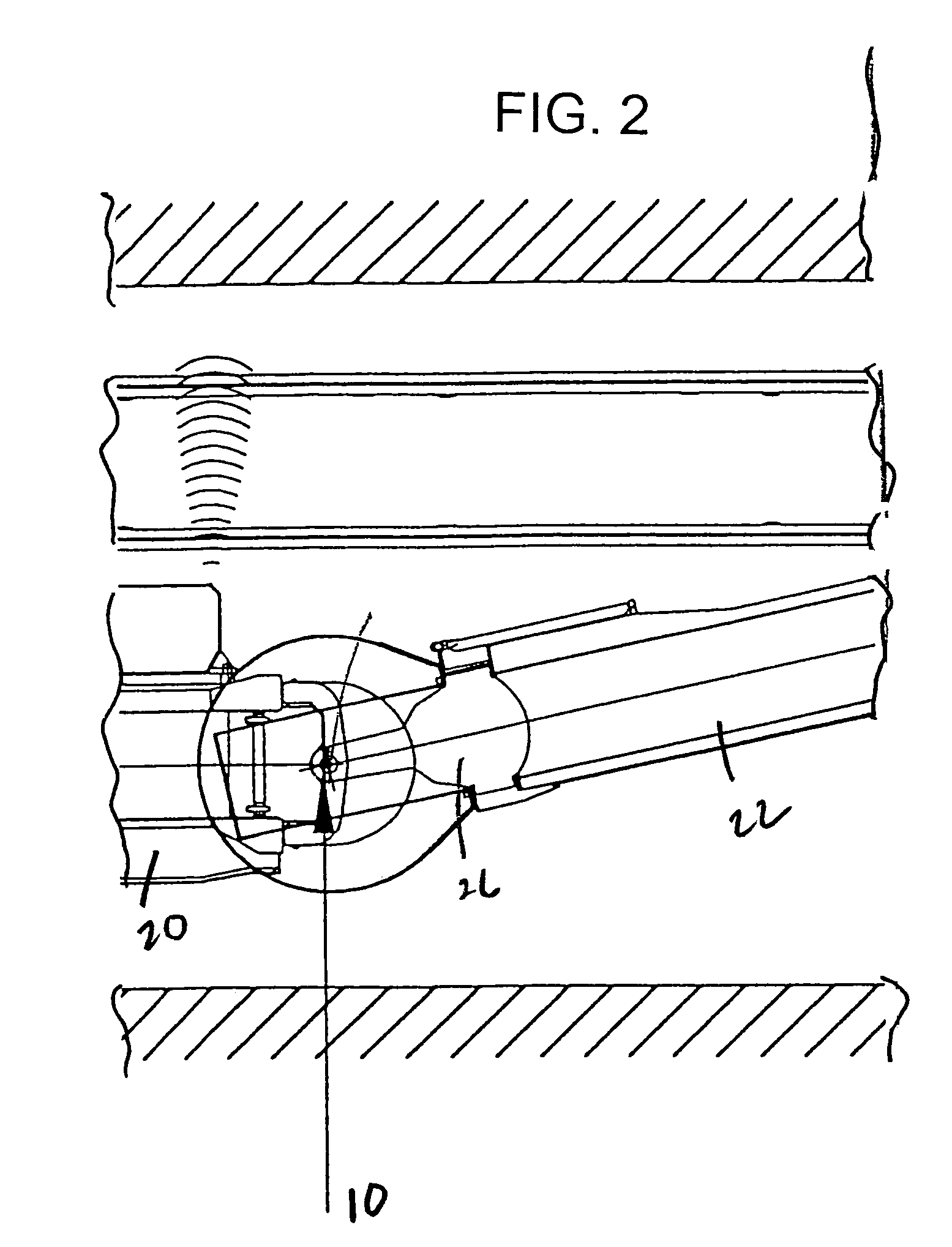
[0027]Referring to FIGS. 1 and 3 of the drawings, the pivot linkage 10 including a non-contact, rotational angle measurement sensor 11 provided by the present invention is described with reference to an application for measuring the angle between, and thus the angular position of, first and second components of a mechanical linkage joint of heavy machinery. By way of example, the mechanical linkage joint 10 can be that between a mobile vehicle (MBM) 20 of a continuous hauler machine of the type used in underground mining applications and a conveyor unit (CBM) 22 that is coupled to and moves along with the mobile vehicle 20. The continuous hauler machine can be that disclosed in copending application Ser. No. 10 / 950,042, of Michael P. Schindler and Stephen A. Rudinec, which was filed on Sep. 25, 2004, and which is entitled “Computer Controller Continuous Haulage Machine”, which application is incorporated herein by reference. However, the mechanical linkage joint including a rotation...


PUM


Abstract

A pivot linkage including a non-contact, rotational angle measurement magnetoresistive sensor for interconnecting first and second rotating components of heavy equipment or machinery, the pivot joint linkage, including a ball joint or a cylindrical pin joint and the like. The sensor uses includes a permanent magnet incorporated into one portion of the joint for producing a magnetic field and a magnetoresistive sensor incorporated into the other portion of the joint for detecting changes in the direction of the magnetic field in response to relative rotation between the two rotating component.

Description

CROSS-REFERENCE TO RELATED APPLICATION[0001]This application claims priority of provisional application Ser. No. 60 / 611,785, filed on Sep. 21, 2004, which is entitled “Computer Controlled Continuous Haulage Machine”, which application is incorporated herein by reference.BACKGROUND OF THE INVENTIONField of the Invention[0002]The present invention relates generally to sensors, and more particularly to a pivot linkage including a non-contact, rotational angle measurement sensor for heavy machinery.[0003]Various types of angle measurement sensors are known. Conventional angle measurement sensors are susceptible to wear, and as such can be characterized as being of limited life. Moreover, known angle measurement sensors are intolerant of movements in directions other than angular movement. Thus, known angle measurement sensors do not have degree of freedom as to movement that does not include the angle being measured. For example, a conventional angle measurement sensor, such as a potent...

Claims


Application Information

Patent Timeline
IPC IPC(8): G01B7/31
CPCG01D5/00G01B7/31F16C41/007F16C11/0619F16C2233/00
Inventor SCHINDLER, MICHAEL P.
Owner JOY MM DELAWARE INC
Learn More