Uptically variable security devices

An optical coating and optical interference technology, applied in optics, optical components, diffraction gratings, etc., can solve problems such as difficult communication of images and difficult recall of images

Inactive Publication Date: 2003-06-11
光学涂层实验公司
View PDF10 Cites 42 Cited by
  • Summary
  • Abstract
  • Description
  • Claims
  • Application Information

AI Technical Summary

Problems solved by technology

Unfortunately, this added complexity does not increase counterfeiting since such complex images are difficult to communicate and difficult, if not impossible, to recall

Method used


Image

  • Uptically variable security devices
  • Uptically variable security devices
  • Uptically variable security devices

Examples


Embodiment 1

[0106] Optical coatings consisting of color shifting flakes in a polymeric vehicle were formed by downdraw on a light transmissive substrate of PET film containing a holographic image. Pull-down media consists of two parts paint / catalyst and one part shifting flakes. The color shifting flakes used have the color shifting properties of green-to-magenta, blue-to-red and magenta-to-gold.

Embodiment 2

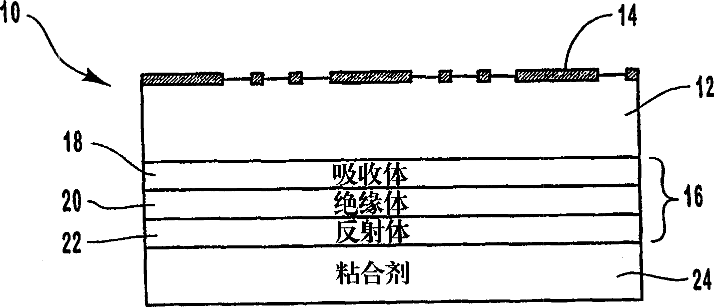
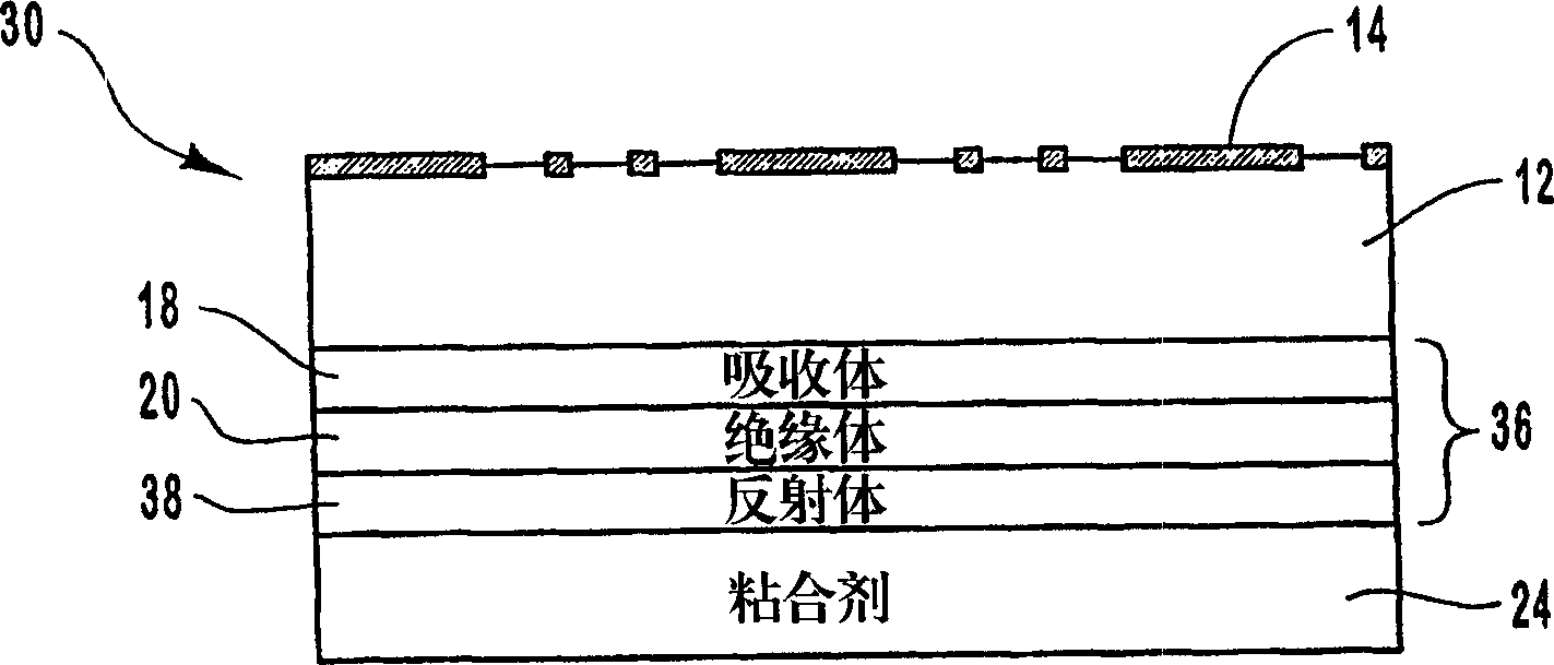
[0108] A color-shifting optical coating with a three-layer structure is formed on an embossed transparent film to produce anti-counterfeiting articles. An optical coating is formed on the plane of the transparent film opposite the embossed surface. The optical coating is formed by depositing an absorbing layer composed of chromium on the plane of the transparent film, depositing an insulating layer composed of magnesium fluoride on the absorbing layer, and depositing an aluminum reflective layer on the insulating layer.

[0109] Alternatively a layer of aluminum can be deposited such that it is substantially transparent. This also allows information printed on the item to be read through the optical coating. In addition, the reflective layer can be made of magnetic material. This magnetic feature in the color shifting composition, when incorporated into the holographic composition, can provide three separate security features to a security article.

[0110] The embossed fil...

Embodiment 3

[0112] According to the present invention, a security article is produced by laminating a laser imaged optical coating to an embossed substrate. The anti-counterfeiting article consists of four main parts:

[0113] 1) laser ablated image, 2) laser ablated barcode or serial number, 3) multilayer color shifting film, and 4) holographic image.

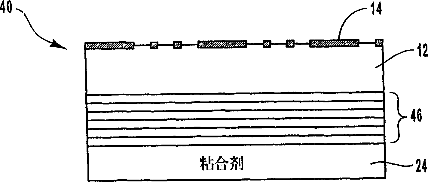
[0114] Color shifting films were deposited on 1 mil thick clear polyester (PET) substrates in a vacuum roll coater. The film is formed by depositing an aluminum metal layer on the substrate, then depositing an insulating layer made of magnesium fluoride on the metal layer, and depositing an absorbing layer made of chromium on the insulating layer. The film was then laser ablated using a laser diode imaging system based on a Heidelberg Quickmaster printing system to provide a digital code. The imaging system uses a high-resolution diode array with a spot diameter of approximately 30 microns. After the digital information has been encode...


PUM

PropertyMeasurementUnit
sizeaaaaaaaaaa
sizeaaaaaaaaaa
thicknessaaaaaaaaaa

Abstract

A security article (10) includes a light transmissive substrate (12) having a first surface and an opposing second surface, with the first surface having an optical interference pattern (14) such as a holographic image pattern or an optical diffraction pattern thereon. A color shifting optical coating (16) is formed on the substrate such as on the interference pattern or on the opposing second surface of the substrate, with the optical coating providing an observable color shift as the angle of incident light or viewing angle changes. Various processes can be utilized to form the security article (10), such as vacuum coating processes, lamination, laser scribing, and laser imaging. The security article (10) can be affixed to a variety of objects through various attachment mechanisms, such as pressure sensitive adhesives or hot stamping processes, to provide for enhanced security measures such as anticounterfeiting.

Description

technical field [0001] The present invention relates generally to thin film optical coatings for use in the manufacture of security articles. In particular, the invention relates to the fabrication of diffractive surfaces such as holograms or gratings with color shifting or optically variable backgrounds that can be used as security articles in various applications. Background technique [0002] Color shifting pigments and colorants are already used in many applications ranging from automotive paints to security inks for security documents and currency. Such pigments and colorants have the property of changing color when the angle of incident light changes or the viewing angle of the observer shifts. The main method used to obtain such color shifting colorants is to disperse the flakes in a medium, such as paint or ink, and then apply the medium to the surface of the object, wherein the flakes generally consist of multilayer films with specific optical properties . [000...

Claims


Application Information

Patent Timeline
Patent Type & Authority Applications(China)
IPC IPC(8): B42D25/30B42D15/00B42D15/10B42D25/328G02B5/18G02B5/28G03H1/18G03H1/26
CPCG03H2250/36G03H2250/34G03H1/0256G03H2250/42G03H2250/40G03H1/0244B42D25/355B42D2035/24G03H2250/10B42D25/328B42D25/00B32B27/36B42D25/29G03H1/0252B42D25/36B42D25/378B42D25/41B42D25/425B42D25/47Y10T428/24479Y10T428/24942Y10T428/25B42D25/30B42D25/21B42D25/23B42D25/24B42D25/455
Inventor 罗杰·W·菲利普斯理查德·L·邦科夫斯基帕特里克·K·希金斯查尔斯·T·马尔坎特斯
Owner 光学涂层实验公司
Why Eureka
Try Eureka