
Self aligned wrap around shield for perpendicular magnetic recording

a perpendicular magnetic recording and shield technology, applied in the field of self-aligning wrap around shield for perpendicular magnetic recording, can solve the problems of reducing the efficiency of the magnetic recording, affecting the stability of the recording, so as to achieve the effect of reducing the switching field and preventing flux leakag

Inactive Publication Date: 2010-01-19
WESTERN DIGITAL TECH INC
View PDF16 Cites 67 Cited by
  • Summary
  • Abstract
  • Description
  • Claims
  • Application Information

AI Technical Summary

Benefits of technology

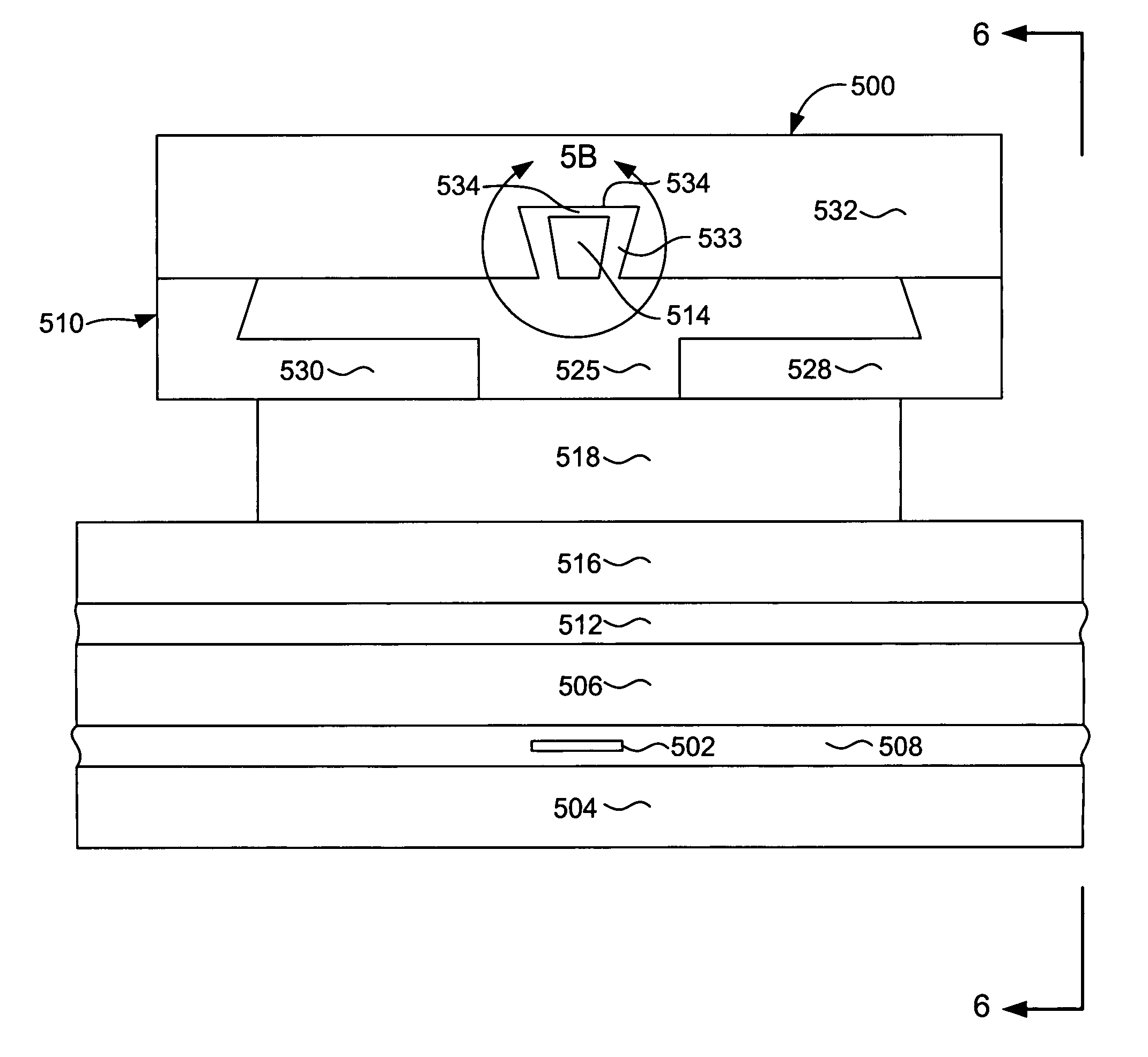
The present invention provides a magnetic write element for perpendicular magnetic recording. The write element includes a magnetic write pole and a wrap around trailing shield. The thickness of the trailing shield gap can be different from the side gaps to provide sufficient write field canting while preventing flux leakage. The trailing edge gap can be made of a non-magnetic material having an ion mill rate similar to that of the write pole. The side gap can be made of a non-magnetic material that can be conformally deposited. The wrap around shield can be a full or partial wrap around shield. The technical effects of the invention include improved data storage capacity and performance of magnetic recording devices.

Problems solved by technology

Simultaneously controlling the flare point and control the track-width of the write pole, utilizing conventional methods of fabrication, such as ion milling, is problematic.
Thus, reducing the width and / or length of the write pole tip may create a magnetic field adjacent to the bit but outside of the track in which the writing process is taking place, thereby corrupting the bits on adjacent tracks.
Similarly, it becomes more difficult to simultaneously maintain the planarity of the trailing edge of the write pole as the width and / or length is decreased using an ion mill approach.
A reduction in the quality of the trailing edge may reduce the quality of the linear transition between each bit.

Method used


Image

  • Self aligned wrap around shield for perpendicular magnetic recording
  • Self aligned wrap around shield for perpendicular magnetic recording
  • Self aligned wrap around shield for perpendicular magnetic recording

Examples


Embodiment Construction

[0025]Reference will now be made in detail to the embodiments of the invention, examples of which are illustrated in the accompanying drawings. While the invention will be described in conjunction with these embodiments, it will be understood that they are not intended to limit the invention to these embodiments. On the contrary, the invention is intended to cover alternatives, modifications and equivalents, which may be included within the scope of the invention as defined by the appended claims. Furthermore, in the following detailed description of the invention, numerous specific details are set forth in order to provide a thorough understanding of the present invention. However, it is understood that the invention may be practiced without these specific details. In other instances, well-known methods, procedures, components, and circuits have not been described in detail as not to unnecessarily obscure aspects of the invention. For example, it is appreciated that the write head ...


PUM

PropertyMeasurementUnit
thicknessaaaaaaaaaa
thicknessaaaaaaaaaa
thicknessaaaaaaaaaa

Abstract

A write element for use in perpendicular magnetic recording. The write element including a write pole and a self aligned wrap around shield that can have a trailing shield gap thickness that is different from its side shield gap thickness. The materials making up the trailing shield gap and the side shield gaps can be different materials or can be the same material deposited in two different steps. The side or wrap around portions of the trailing shield can extend down to the level of the leading edge of the write pole or can terminate at some point between the levels of the leading and trailing edge to form a partial wrap around trailing shield.

Description

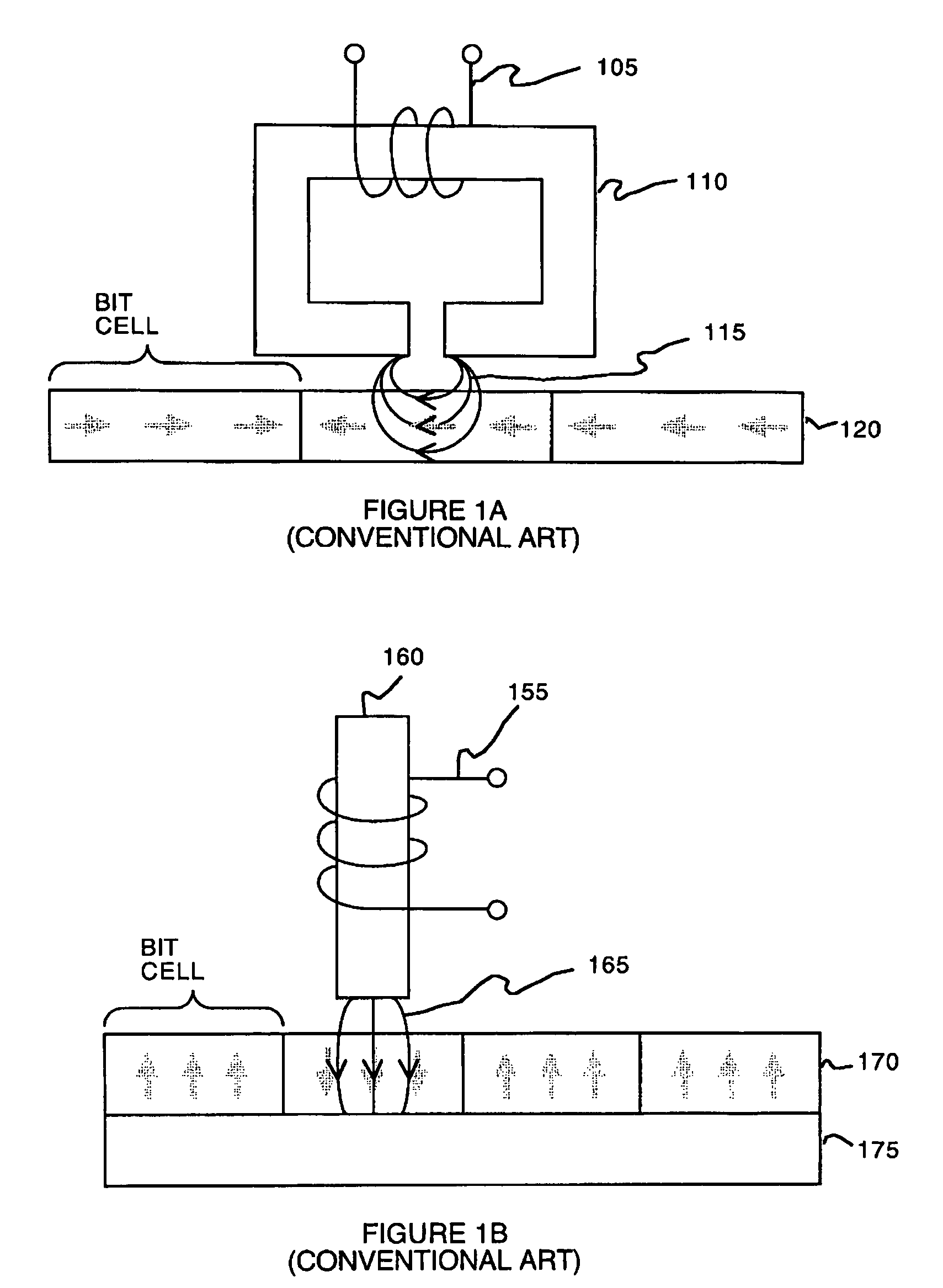
[0001]This is a Continuation In Part of pending commonly assigned patent application Ser. No. 10 / 931,649, filed Aug. 31, 2004, entitled WRITE POLE AND METHOD OF MANUFACTURING THE SAME, by Le et al.BACKGROUND OF THE INVENTION[0002]Magnetic heads are used in disk drives to write information on to a moving magnetic media and to read the information stored thereon. Conventional magnetic heads include a write head and a read head. A write head should be capable of writing straight and sharp transitions. The write head should also be capable of writing the data on a given track without reducing the signal of adjacent or nearby tracks.[0003]The write head may implement a longitudinal recording mode or a perpendicular recording mode for magnetically encoding data on a disk. A longitudinal write head, in accordance with the conventional art, is depicted in FIG. 1A. In longitudinal recording, a coil 105 wound around a toroid 110 generates a magnetic flux. The fringe field 115 proximate a gap ...

Claims


Application Information

Patent Timeline
Patent Type & Authority Patents(United States)
IPC IPC(8): G11B5/33
CPCG11B5/1278G11B5/1475G11B5/23G11B5/3163G11B5/315G11B5/3116
Inventor LE, QUANGSUN, NIAN-XIANGZOLLA, HOWARD GORDON
Owner WESTERN DIGITAL TECH INC
Learn More