Flux concentrated-type motor

a concentrated type, motor technology, applied in the direction of windings, magnetic circuit rotating parts, magnetic circuit shape/form/construction, etc., can solve the problem of limited back electromotive force, and achieve the effect of reducing production costs, facilitating miniaturization of products, and improving torqu

Inactive Publication Date: 2006-03-23
LG ELECTRONICS INC
View PDF7 Cites 11 Cited by
  • Summary
  • Abstract
  • Description
  • Claims
  • Application Information

AI Technical Summary

Benefits of technology

[0025] The flux concentration-type motor of the present invention, which comprises the flux concentration-type rotor including a plurality of the magnets arranged in the circumferential direction such that the same poles of the magnets face each other, so as to prevent the leakage of magnetic flux of the magnets, thereby improving the torque compared to a conventional surface mounted permanent magnet-type motor having the same volume, reducing the production costs, and facilitating the miniaturization of products.
[0026] Further, since the flux barrier is installed in the rotor core of the motor for maximally preventing the leakage of magnetic flux of the magnets, the flux concentration-type motor of the present invention improves the overall performance thereof due to the improvement of the torque thereof.

Problems solved by technology

This is caused by the structure of the surface mounted permanent magnet-type motor, i.e., since the increase of the length of the overhang increases the amount of the magnetic flux, which is not interlinked with the coils and leaked through other portions.
However, since the effects of the overhang are lost when the length of the overhang is increased to a designated value or more, the conventional surface mounted permanent magnet-type motor is disadvantageous in that the increase of the back electromotive force is limited.

Method used


Image

  • Flux concentrated-type motor
  • Flux concentrated-type motor
  • Flux concentrated-type motor

Examples


Embodiment Construction

[0037] Now, a preferred embodiment of a permanent magnet-type motor in accordance with the present invention will be described in detail with reference to the annexed drawings.

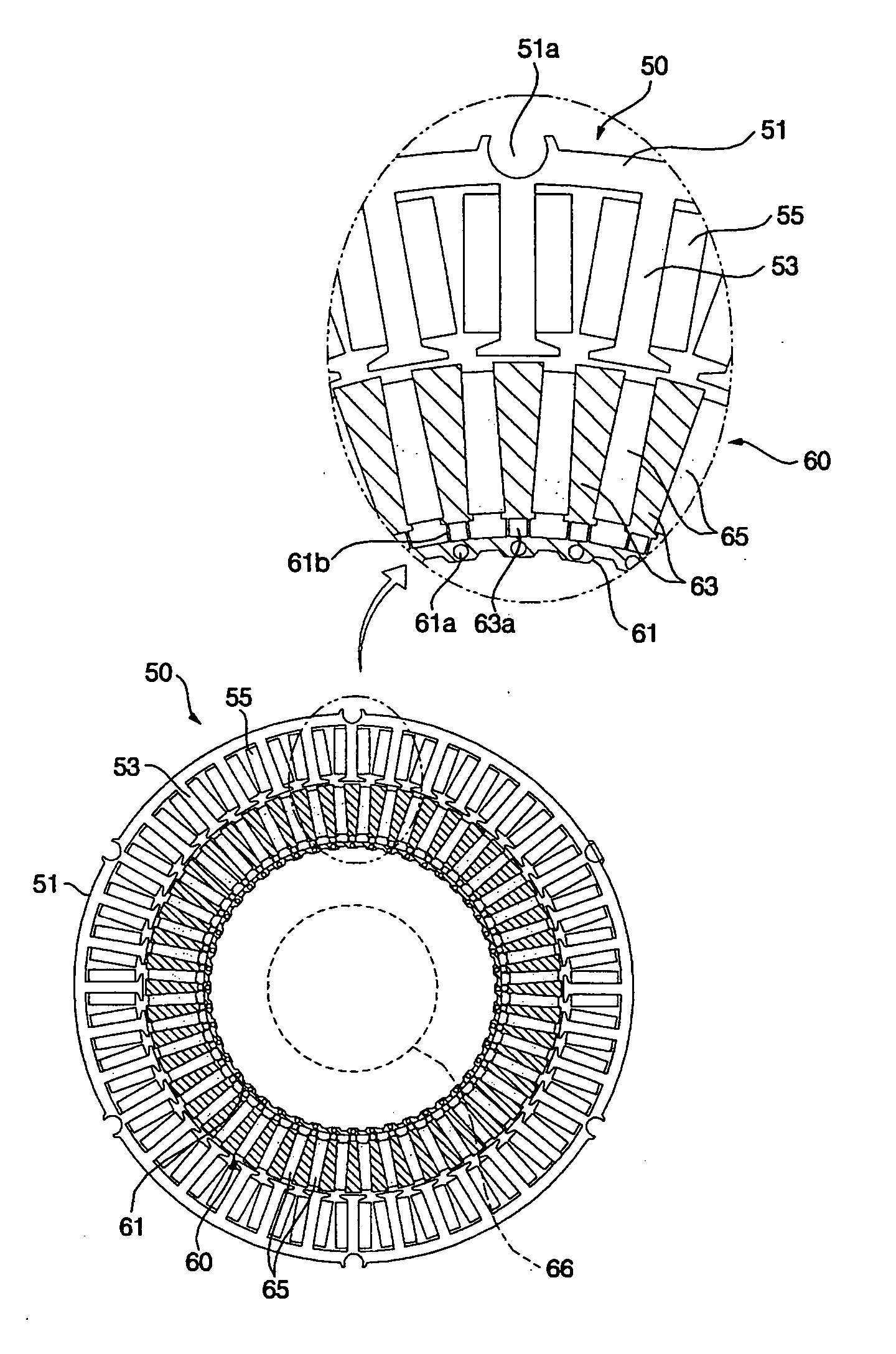
[0038]FIG. 5 is a plan view of a flux concentration-type motor in accordance with the present invention.

[0039] The flux concentration-type motor of the present invention comprises a ring-shaped stator 50 having a plurality of teeth 53 formed in a radial direction and coils 55 wound on the teeth 53, and a rotor 60 located at the center of the stator 50, including a plurality of magnets arranged in a circumferential direction such that the poles, having the same polarity, of the magnets face each other, and rotated by the interaction with the coils 55 of the stator 50.

[0040] The stator 50 includes a ring-shaped core 51 forming an external appearance, a plurality of the teeth 53 protruded from the inner circumferential surface of the core 51 toward the rotor 60 and arranged in the radial direction, and the coi...


PUM


Abstract

A flux concentration-type motor includes a ring-shaped stator, in which coils are wound on a plurality of teeth radially arranged; and a rotor, located at the center of the stator, having a plurality of magnets arranged in a circumferential direction such that poles, having the same polarity, of the magnets face each other, and rotated by the interaction with the stator, so as to prevent the leakage of magnetic flux of the magnets, thereby improving the torque compared to a conventional surface mounted permanent magnet-type motor having the same volume, reducing the production costs, and facilitating the miniaturization of products.

Description

BACKGROUND OF THE INVENTION [0001] 1. Field of the Invention [0002] The present invention relates to a motor for driving a washing machine, and more particularly to a flux concentration-type motor having an internal rotatable structure. [0003] 2. Description of the Related Art [0004] Generally, permanent magnet-type motors are divided into a surface mounted permanent magnet-type motor and an interior permanent magnet-type motor according to the configurations of magnetic circuits. [0005] A motor for directly driving employs a washing machine an outer rotor-fashioned, surface mounted, and permanent magnet-type motor. [0006]FIGS. 1 and 2 illustrate a motor for driving a washing machine. FIGS. 1 and 2 are respectively exploded perspective and plan views of an external rotatable motor, which is one type of the conventional surface mounted, permanent magnet-type motors. [0007] The above surface mounted permanent magnet-type motor, in which a rotor 20 is installed outside a stator 10, mai...

Claims


Application Information

Patent Timeline
Patent Type & Authority Applications(United States)
IPC IPC(8): H02K7/00H02K1/27
CPCH02K21/16H02K1/2773H02K3/522H02K15/03
Inventor LEE, SUNG HOPARK, JIN SOOKIM, YOUNG KWANKIM, DEOK JIN
Owner LG ELECTRONICS INC
Why Eureka
Try Eureka