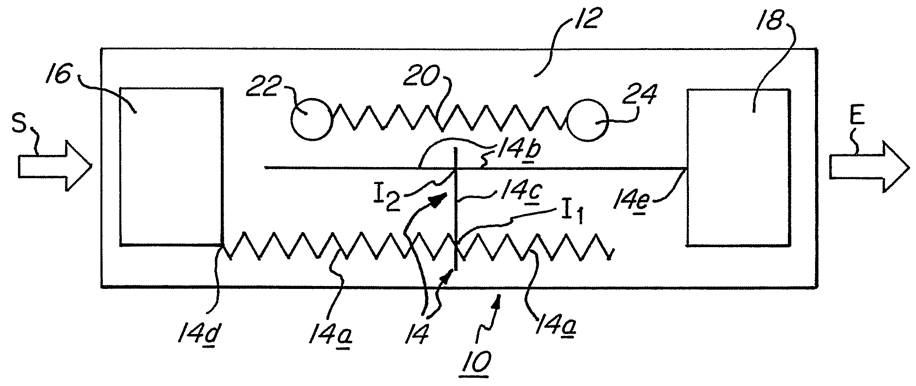
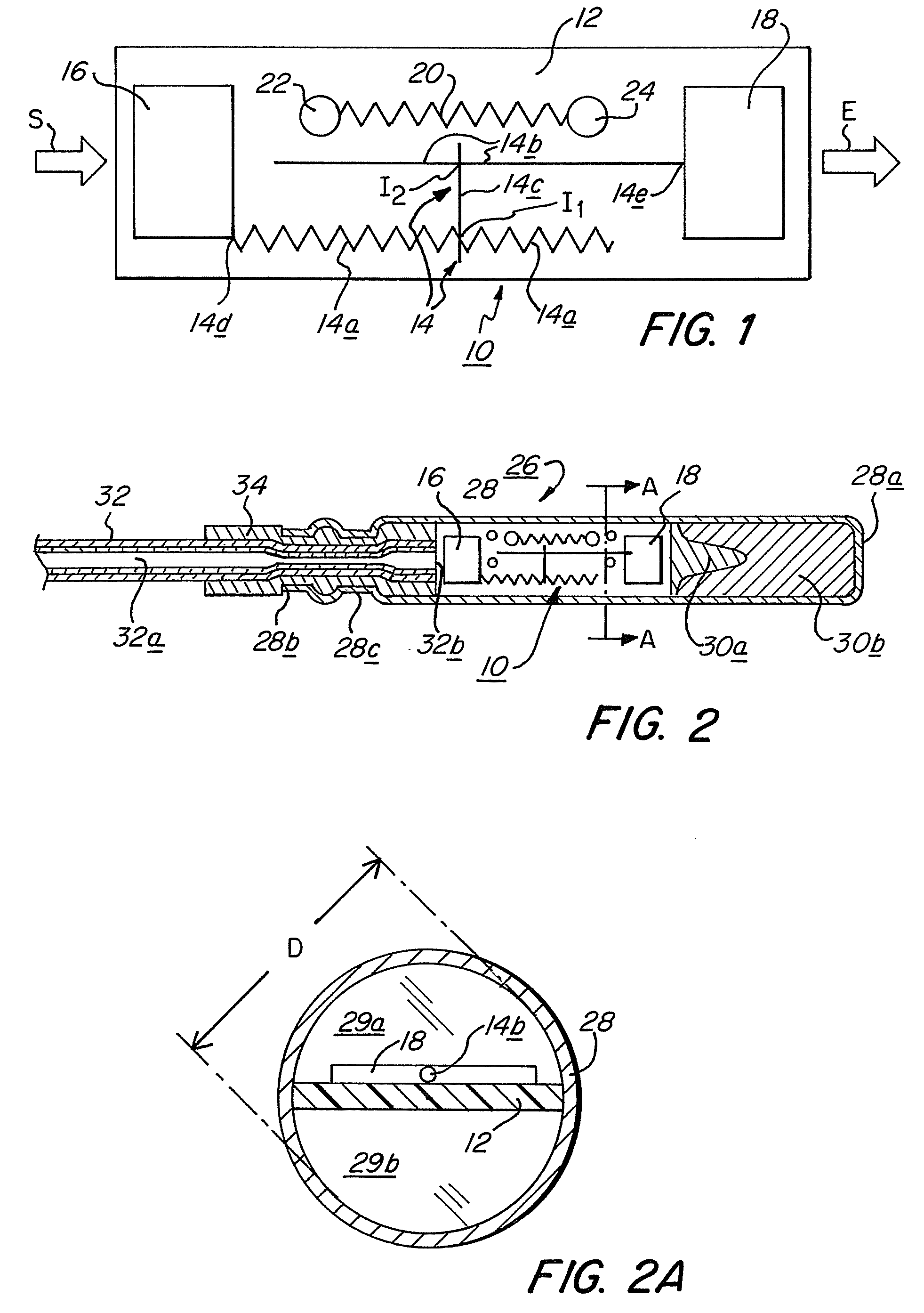
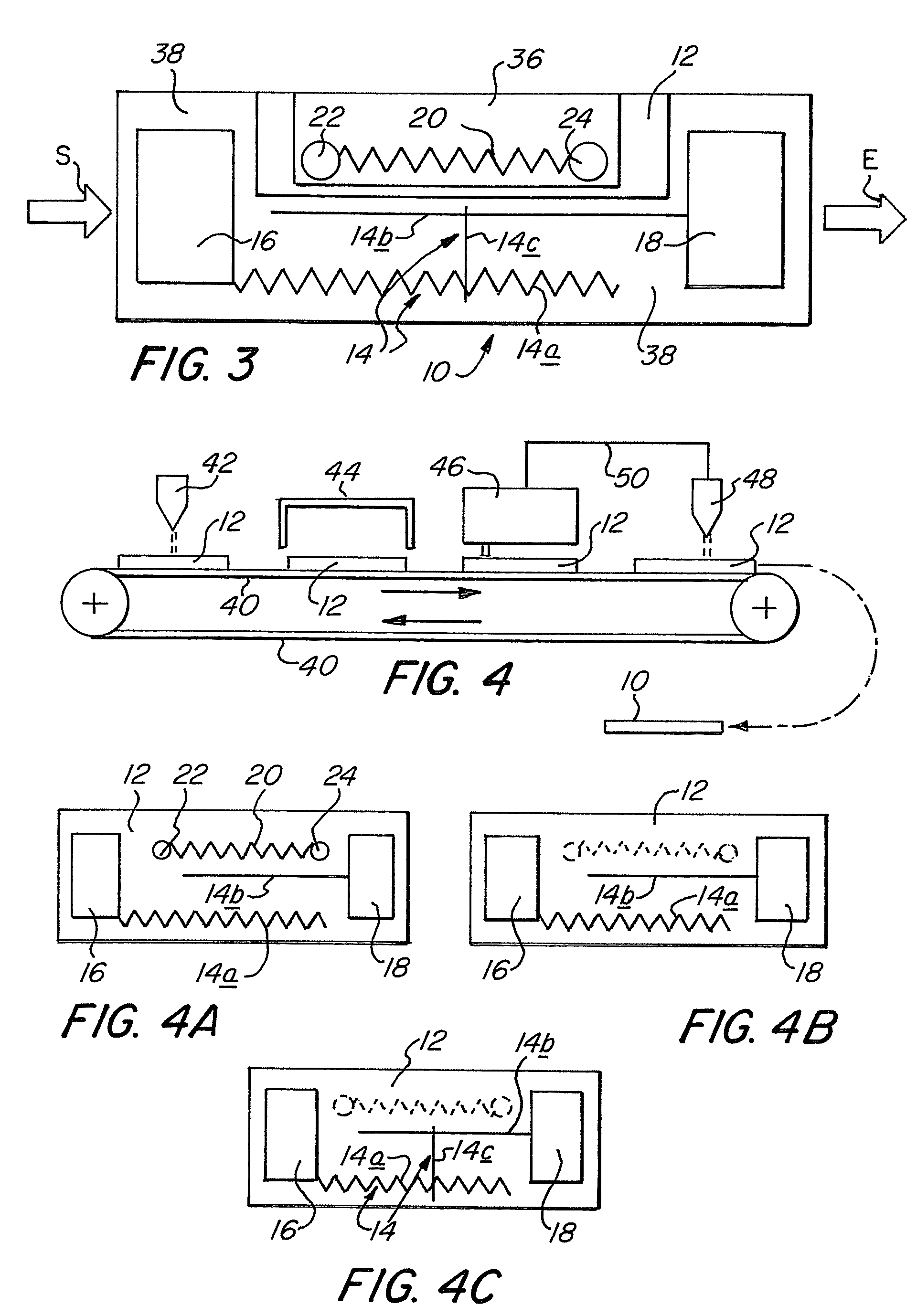
[0060]A significant advantage of the present invention is that it enables adjusting the timing strip, such as timing strip 14, based on the result attained by functioning the calibration strip, such as calibration strip 20. This adjustment may be carried out in a number of different ways as described below in connection with certain of the Figures. Generally, adjusting the timing strip may comprise one or more of adding to it an accelerant or a decelerant to either increase or decrease the burn rate of the timing strip; providing one or more jump gaps in the timing strip to slow down the burn rate, adjusting the effective length of the timing strip either by initially applying only a portion of the timing strip and completing the timing strip so as to impart to it a selected effective length based on the burn rate as determined by functioning the calibration strip or positioning one or both of charges, such as charges 16 and 18 described below, to leave between them a desired uncovered (by the charges) effective length of the timing strip.
[0061]Timing strip 14 has a starting point 14d and a discharge point 14e. The “effective length” of a timing strip is the continuous length along the timing strip between its starting point and discharge point. Thus, the effective length of timing strip 14 starts at starting point 14d, traverses a portion of first strip 14a to a first intersection point I1 with bridging strip 14c, traverses a portion of bridging strip 14c to a second intersection point I2 with second strip 14b, and then traverses that portion of second strip 14b between the second intersection point 12 and discharge point 14e. It is seen that terminal portions of strips 14a and 14b are excluded from the effective length of timing strip 14 because of the particular location of intersection points I1 and I2 in the illustrated embodiment. Similarly, terminal ends of bridging strip 14c are excluded from the effective length of timing strip 14 because they extend slightly beyond the first and second intersection in order to insure a good connection between bridging strip 14c and strips 14a and 14b.
[0062]Starting point 14d is connected in signal transfer communication to a pick-up charge 16 disposed on substrate 12, and discharge point 14e is in signal transfer communication with a relay charge 18 also disposed on substrate 12. Pick-up charge 16 and relay charge 18 may be printed on substrate 12 in a manner similar or identical to that used to print timing strip 14 and calibration strip 20. Alternatively, charges 16 and 18 may be applied to substrate 12 by any other suitable means. Charges 16 and 18 may, but need not, be comprised of energetic nano materials.
[0063]In the various embodiments of the invention, the timing strip is deposited on the substrate and has a starting point which is positioned to receive an input signal, and a discharge point which is spaced from the starting point and positioned to initiate an output signal. The length of the timing strip between the starting point and the discharge point, i.e., the longitudinal distance along the timing strip between its starting and discharge points, is its effective length; the burn time of the effective length of the timing strip determines the time delay between the timing strip's receipt of the input signal and its initiation of the output signal. The timing strip may be configured in a straight, curved, zig-zag or other pattern, to provide a desired effective length of the timing strip. The substrate may optionally be a reactive substrate which participates in or contributes to the reaction of the energetic material in the timing strip (and, optionally, in a calibration strip, as described below).
[0064]Generally, the pick-up charge at the starting point of the timing strip is in signal transfer relationship with the output of a signal transmission fuse, and the relay charge at the discharge point of the timing strip is in signal transfer communication with an output explosive charge of an explosive device, such as a delay detonator, incorporating the delay unit of the invention. Thus, generally, one or both of: (1) a pick-up charge is disposed in signal transfer communication between the output of a signal transmission fuse and the starting point of the timing strip, and (2) a relay charge is disposed in signal transfer communication with the discharge point of the timing strip. The pick-up and relay charges may be deposited on the substrate by printing or any other suitable means.
[0065]The saw-tooth configuration of some of the strips is used simply to provide a longer effective length of strip within the limited area provided by substrate 12. Obviously, any suitable pattern of strips (spiral, serpentine, etc.) may be utilized. Substrate 12 may, of course, be of any size suitable for the intended use of the delay unit. For a delay unit which is intended for use in a standard size detonator shell, as described below, substrate 12 would typically have a width selected to approximate the inside diameter of the detonator shell so as to fit snugly therein. A mounting frame (not shown in the drawings) sized to snugly fit within the detonator shell may optionally be utilized to support the substrate 12 which would be appropriately sized to fit the mounting frame. Substrate 12 would typically have a length of from about one-quarter inch (0.64 cm) to about 1.2 inches (3.05 cm) to easily fit within a standard size detonator shell. Substrate 12, which may be made of conventional printed circuit board, need be only thick enough to provide sufficient rigidity and mechanical strength to be manipulated during manufacture and installation in an explosive device without physical distortion of the strips on the active surface. For example, substrate 12 may be from about 1 / 16 to ⅛ inch (0.159 to 0.318 cm) thick. Arrows S and E in FIG. 1 are described below.


