Teatcup liner and a teatcup

a teatcup and liner technology, applied in the field of teatcup liner, can solve the problems of limiting the manufacturing process of teatcup liners, difficult to remove teatcup liners with a conventional design from the mould, and difficult vulcanisation of rubber vulcanisation, so as to achieve quick and reliable assembly of teatcup liner, and efficiently prevent penetration

Active Publication Date: 2010-01-26
DELAVAL HLDG AB
View PDF14 Cites 23 Cited by
  • Summary
  • Abstract
  • Description
  • Claims
  • Application Information

AI Technical Summary

Benefits of technology

[0009]This object is achieved by the teacup liner initially defined, which is characterised in that the connecting ring of at least one of the components abuts the peripheral portion of the other component to form a sealing abutment between the primary component and the secondary component. Such a sealing abutment between one of the peripheral portions, which may be made in a relatively elastic and soft material, and one of the connecting rings, which may be made in a relatively rigid material, offers a tight and reliable joint between the two components. Advantageously, the primary connecting ring abuts the secondary peripheral portion to form a first sealing abutment, and the secondary connecting ring abuts the primary peripheral portion to form a second sealing abutment. In such a way two tight and reliable joints are provided between the two components.
[0012]According to a further embodiment of the invention, the primary connecting ring includes a primary engagement member and the secondary connecting ring includes a secondary engagement member, wherein the engagement members are in engagement with each other when the primary component is connected to the secondary component. Advantageously, the engagement members are adapted to engage each other by means of a snap action. In such a way a quick and reliable assembly of the teatcup liner is achieved.
[0013]According to a further embodiment of the invention, the primary peripheral portion has an inner peripheral surface adjoining the inner space. Furthermore, the secondary connecting ring may have an inner peripheral surface adjoining the inner space and being in alignment with the inner peripheral surface of the primary peripheral portion. With such a uniform inner transition between the primary and secondary components, dirt and milk residuals are efficiently prevented from penetrating the joint between the components from the inner space.
[0014]According to a further embodiment of the invention, the secondary peripheral portion has an annular projection extending downwardly and adapted to be positioned in an annular recess of the shell when the teatcup liner is mounted in the shell. In such a way a further sealing abutment is obtained between the shell and the secondary peripheral portion of the secondary component. The airtight enclosure of the pulsation chamber between the shell and the secondary component is therefore further improved. The annular projection may advantageously be provided beneath the outer peripheral surface of the secondary peripheral portion.
[0015]According to a further embodiment of the invention, the primary peripheral portion has a substantially radial surface adapted to abut a corresponding radial surface of the shell when the teatcup liner is mounted in the shell. In such a way a sealing abutment is obtained between the shell and the primary peripheral portion preventing dirt, milk residual or micro-organisms from penetrating the joint from outside. Advantageously, the substantially radial surface may be provided outside the outer peripheral surface of the primary connecting ring.

Problems solved by technology

However, the vulcanisation of the rubber requires a significant vulcanisation time before the rubber can be removed from the mould and the core.
This is a limiting factor in the manufacturing of teatcup liners.
However, the elasticity of thermoplastic materials is generally smaller than the elasticity of rubber, which means that a teatcup liner with a conventional design would be difficult to remove from the mould, and in particular the from core, after the solidification.
No particular measures have been taken to obtain a reliable and tight sealing between the head portion and the barrel portion.

Method used


Image

  • Teatcup liner and a teatcup
  • Teatcup liner and a teatcup
  • Teatcup liner and a teatcup

Examples


Embodiment Construction

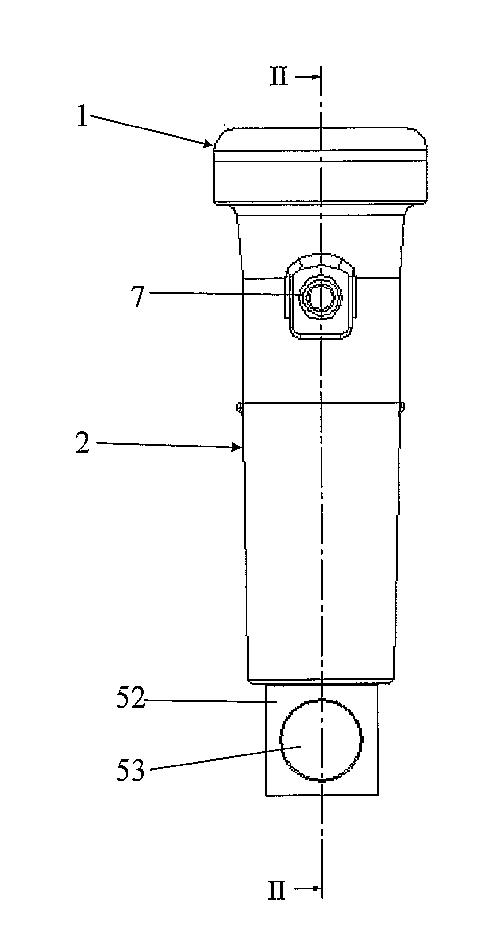
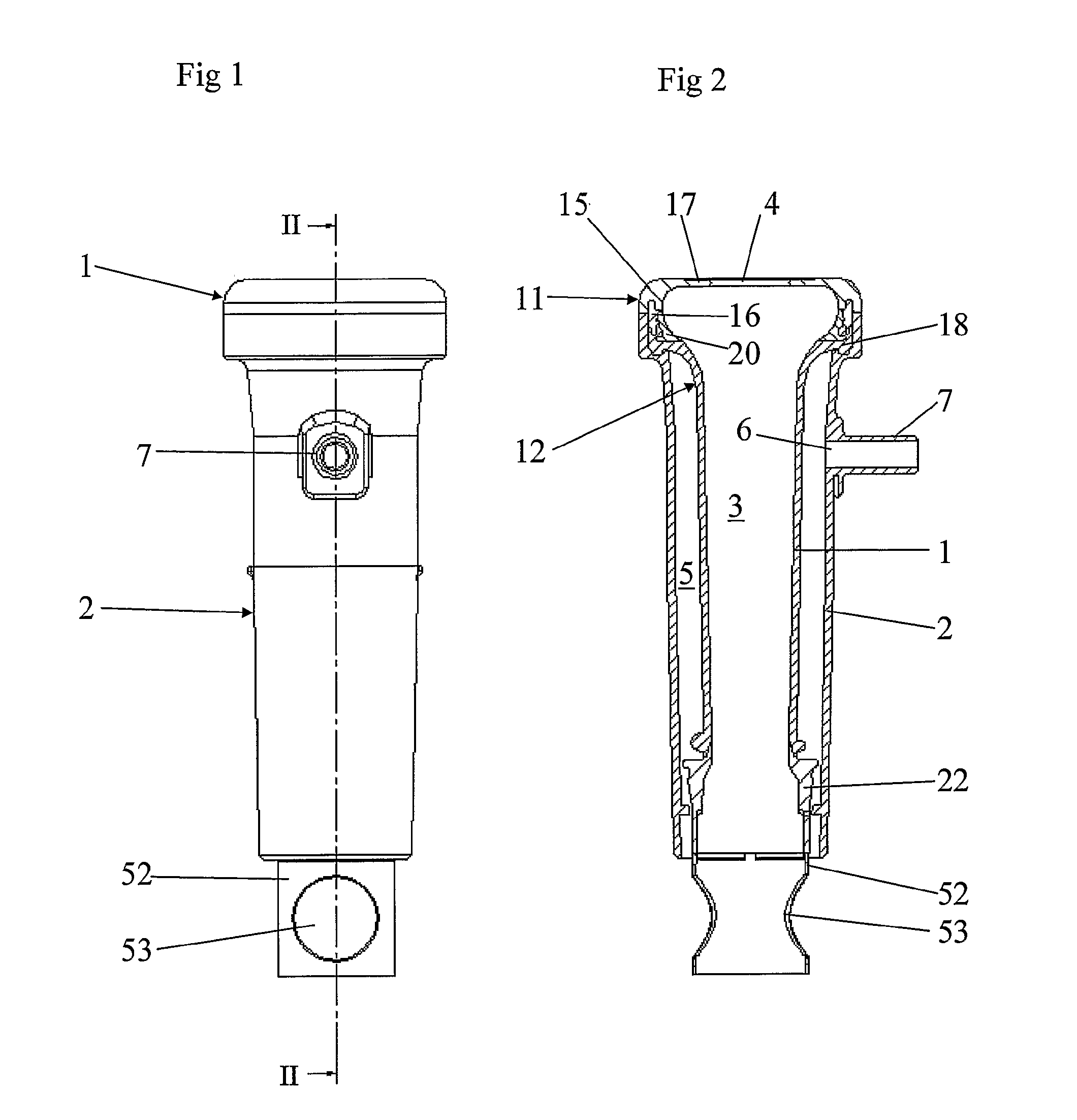
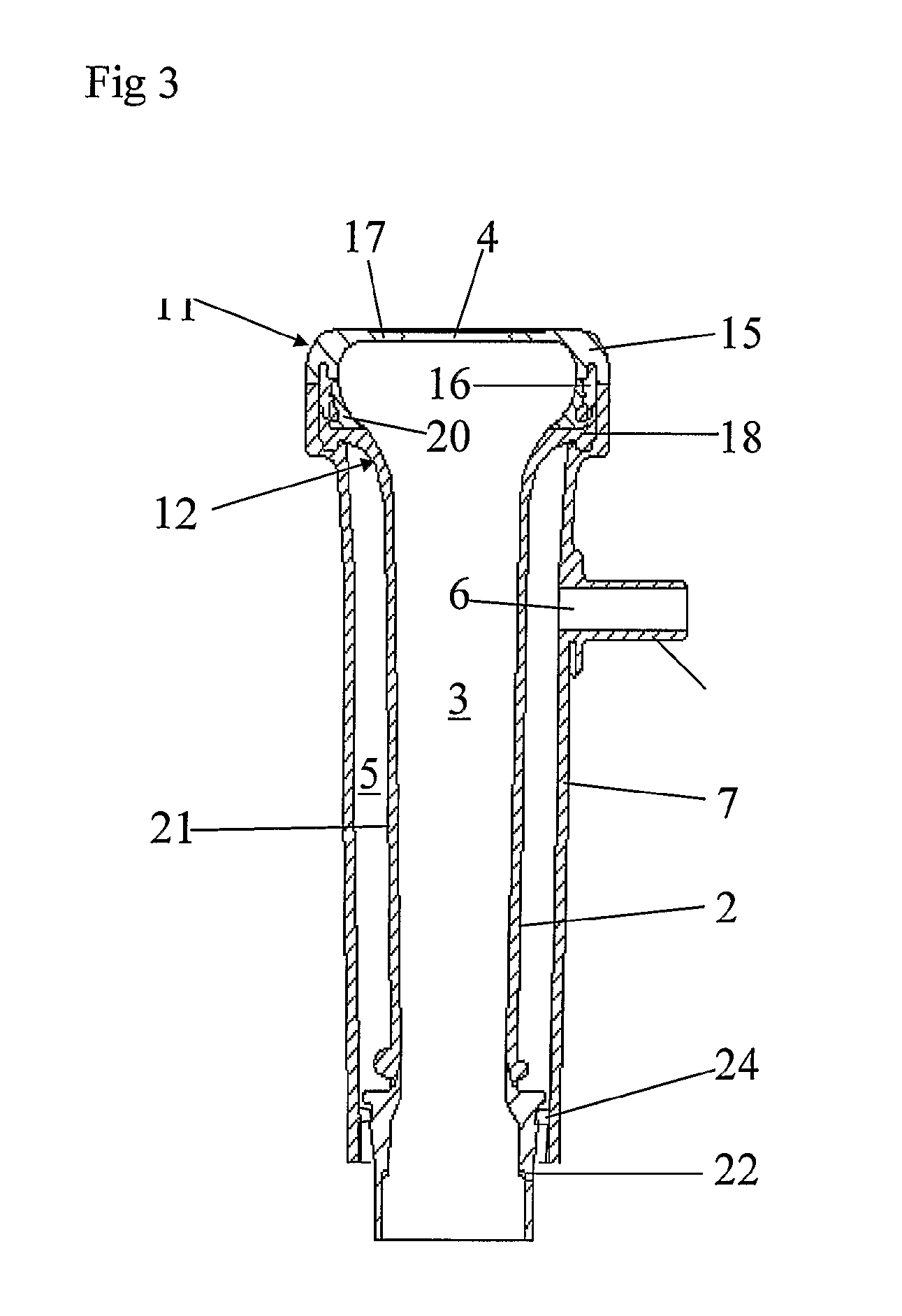
[0027]FIGS. 1 and 2 disclose a teatcup during mounting thereof. The teatcup includes a teatcup liner 1 and a shell 2. In FIG. 3, the teatcup liner 1 is completely mounted in the shell 2. The teatcup includes an inner space 3 defined by the teatcup liner 1 and adapted to receive a teat of an animal to be milked. The teat is introduced into the inner space 3 via an opening 4. A pulsation chamber 5 is formed between the shell 2 and the teatcup liner 1, as appears from FIG. 3. The pulsation chamber 5 is accessible via an aperture 6, which in the embodiment disclosed is formed by a pulsation nipple 7. In use, the teatcup is, as disclosed in FIG. 3, intended to be mounted in a holding device (not disclosed), which connects the inner space 3 of the teatcup to a milk conduit (not disclosed) for the application of a low pressure or vacuum and for the transport of milk from the teat present in the inner space 3. The pulsation nipple 7 may be directly connected to a pulsation conduit (not disc...


PUM


Abstract

This invention refers to a teatcup liner and a teatcup. The liner (1) is mounted in a shell (2) of the teatcup and defines an inner space (3) for receiving a teat. The liner includes a primary component (12) forming a barrel. The primary component includes a peripheral portion (15), a primary connecting ring (16) and a lip (17) defining an opening (4). The secondary component includes a secondary peripheral portion (18) and a secondary connecting ring (20). The primary component is connectable to the secondary component for releasing the liner by a mutual engagement of the connecting rings. At least one of the connecting rings abuts the peripheral portion of the other component to form a sealing abutment between the two components.

Description

[0001]Applicant hereby incorporates by reference International Application PCT / SE2005 / 000747, filed 19 May 2005, claiming priority from Swedish Application No. SE 0401484-1 filed 10 Jun. 2004 (also incorporated by reference herein).BACKGROUND OF THE INVENTION AND PRIOR ART[0002]The present invention refers to a teatcup liner adapted to be mounted in a shell to form a teatcup to be applied to a teat of an animal, the teatcup liner defining an inner space for receiving the teat and including a primary component forming an upper head of the teatcup liner and a secondary component forming a lower barrel of the teatcup liner, the primary component including a primary peripheral portion, a primary connecting ring extending downwardly from the primary peripheral portion, and a lip extending inwardly from the primary peripheral portion and defining an opening for the introduction of the teat, the secondary component including a secondary peripheral portion and a secondary connecting ring ex...

Claims


Application Information

Patent Timeline
Patent Type & Authority Patents(United States)
IPC IPC(8): A01J5/06A01JA01J5/08
CPCA01J5/08
Inventor PETTERSON, TORBJORNKASSIBRAHIM, JAN
Owner DELAVAL HLDG AB
Why Eureka
Try Eureka