Scroll

A technology for rewinding shafts and main shafts, which is applied in the field of serially mounted pneumatic rewinding reels, which can solve the problems that materials are prone to breakage, rewinding expansion force cannot be zero, and parts are easy to be lost.

Inactive Publication Date: 2010-01-13
江阴市申港电讯器材厂
View PDF0 Cites 2 Cited by
  • Summary
  • Abstract
  • Description
  • Claims
  • Application Information

AI Technical Summary

Problems solved by technology

[0002] At present, there are many kinds of domestic and imported reels used in the market that adopt the airbag type rewinding method. To expand the paper tube, plastic tube or steel tube, it must be pre-inflated, that is, the initial rewinding force cannot be zero. If If the rewinding expansion force is small, it cannot ensure that the paper tube, plastic tube or steel pipe can be tightened. Moreover, the rewinding shaft after the above-mentioned pre-inflation has a large initial expansion force, so when winding thin or narrow materials, the material will be extremely damaged. It is easy to break, and the parts of the friction pair of the above-mentioned rewinding shaft are easy to wear and tear, and the frequent replacement will increase the maintenance cost. The minimum width of the above-mentioned rewinding is generally about 30mm, which seriously affects its scope of use.

Method used


Image

  • Scroll
  • Scroll
  • Scroll

Examples


Embodiment Construction

[0030] The present invention is described in further detail below in conjunction with the embodiment that accompanying drawing provides.

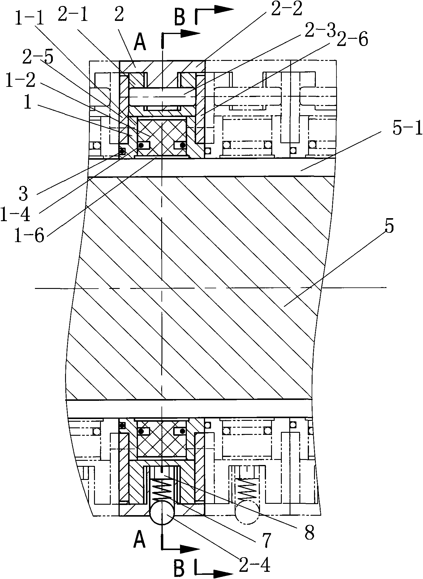
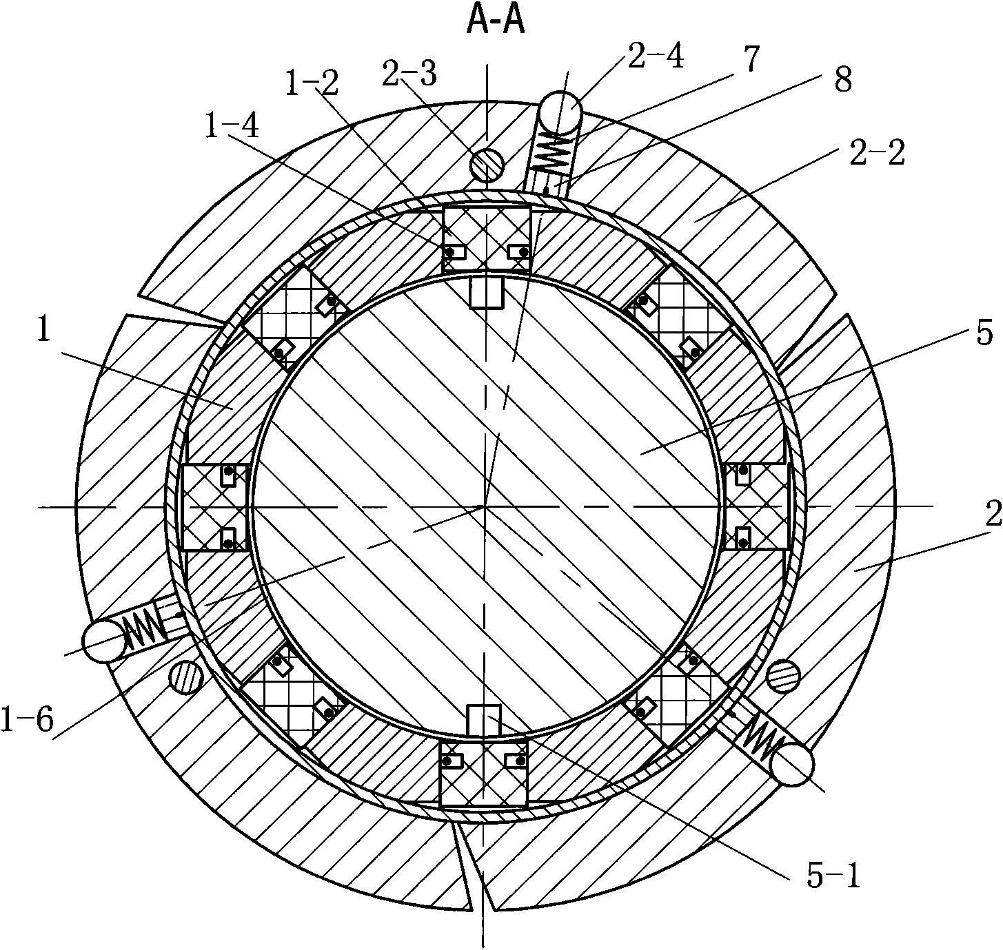
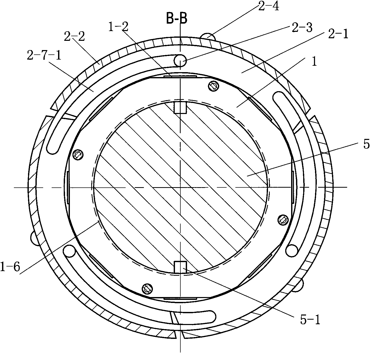
[0031] see Figure 1-16 As shown, a winding shaft is composed of a plurality of friction pairs mounted in series on a main shaft 5 with an air inlet passage 5-1. The friction pairs include a fixed ring 1, and the fixed ring 1 includes a ring body 1-1, a piston 1-2 and piston sealing ring 1-4, the ring body 1-1 is set on the main shaft 5, both sides of the ring body 1-1 have annular steps 1-1-1, and the ring body 1-1 is evenly distributed in the circumferential direction There are at least six radial piston holes 1-5, and each radial piston hole 1-5 is equipped with a piston 1-2 with a piston sealing ring 1-4, and one end of the radial piston hole 1-5 is connected to the air inlet The channel 5-1 is connected, and the other end is the inlet and outlet hole of the piston 1-2; the friction pair also includes an expansion ring 2 used in conjun...


PUM


Abstract

The invention discloses a scroll which is formed by serially installing a plurality of rubbing pairs on a main shaft with an air intake channel. The rubbing pairs comprise a fixed ring and an expansion ring, wherein the expansion ring is matched with the fixed ring, the expansion ring is sleeved on the fixed ring, and a first annular cover plate and a second annular cover plate limiting the expansion ring to make axially displacement are fixedly connected at the two sides of a ring body. The expansion ring comprises an expansion ring seat, an arc slider, a connecting member and a rubbing member, wherein the expansion ring seat is provided with a peripheral slider groove, convex shoulders at the two sides of the slider groove are both provided with arc inclined holes, and the corresponding arc inclined holes on the convex shoulders at the two sides of the slider groove are axially communicated; the arc slider of the expansion ring is provided with a connecting member hole, the arc slider is matched with the slider groove in a sliding mode, the connecting member passes through the connecting member hole, and two ends of the connecting member are positioned in the arc inclined holes of the convex shoulders, the arc slider is provided with a radial rubbing member hole with the necking outer end, an elastic member is arranged in the rubbing member hole, and the rubbing member projecting the outer arc surface of the arc slider is movably arranged in the rubbing member hole in a matching mode, therefore, the invention has the advantages of firm expansion and wide use range.

Description

technical field [0001] The invention relates to a series-mounted pneumatic rewinding shaft used in conjunction with mechanical equipment, especially suitable for the mechanical equipment for cutting, winding, unwinding and rewinding of plastics, packaging, paper plastics and ultra-thin metal films, etc. superior. Background technique [0002] At present, there are many kinds of domestic and imported reels used in the market that adopt the airbag type rewinding method. To expand the paper tube, plastic tube or steel tube, it must be pre-inflated, that is, the initial rewinding force cannot be zero. If If the rewinding expansion force is small, it cannot ensure that the paper tube, plastic tube or steel pipe can be tightened. Moreover, the rewinding shaft after the above-mentioned pre-inflation has a large initial expansion force, so when rewinding thin or narrow materials, the material will be extremely tight. It is easy to break, and the parts of the friction pair of the ab...

Claims


Application Information

Patent Timeline
Patent Type & Authority Applications(China)
IPC IPC(8): B65H75/24
Inventor 宋伯祥
Owner 江阴市申港电讯器材厂
Why Eureka
Try Eureka