Rotary part pneumatic tensioning device with shaft positioning function

A tensioning device and technology with a shaft, applied in the components of boring machines/drilling machines, grinding/polishing safety devices, drilling tool accessories, etc., can solve problems such as the inability to realize automatic production, and achieve automatic production, stable and reliable tensioning , The effect of compact installation space

Pending Publication Date: 2021-11-09
BEIJING DEMINA PRECISION MACHINERY
View PDF9 Cites 2 Cited by
  • Summary
  • Abstract
  • Description
  • Claims
  • Application Information

AI Technical Summary

Problems solved by technology

[0002] For the grinding of the chamfered edge of the drill bit blade made of CBN material for oil drilling, the existing devices mostly use chucks or spring chucks for manual clamping, which cannot realize automatic production

Method used


Image

  • Rotary part pneumatic tensioning device with shaft positioning function
  • Rotary part pneumatic tensioning device with shaft positioning function

Examples


Embodiment Construction

[0019] Below, in conjunction with the accompanying drawings and specific embodiments, the present invention is further described:

[0020] In the description of the present invention, it should be noted that the terms "top", "bottom", "one side", "the other side", "front", "rear", "middle", "inside", " The orientation or positional relationship indicated by "top", "bottom end", etc. is based on the orientation or positional relationship shown in the drawings, and is only for the convenience of describing the present invention and simplifying the description, rather than indicating or implying that the indicated device or element must have specific orientation, construction and operation in a specific orientation, and therefore should not be construed as a limitation of the present invention; the terms "first", "second", "third" are used for descriptive purposes only and should not be construed as indicating or implying relative Importance; in addition, unless otherwise express...


PUM


Abstract

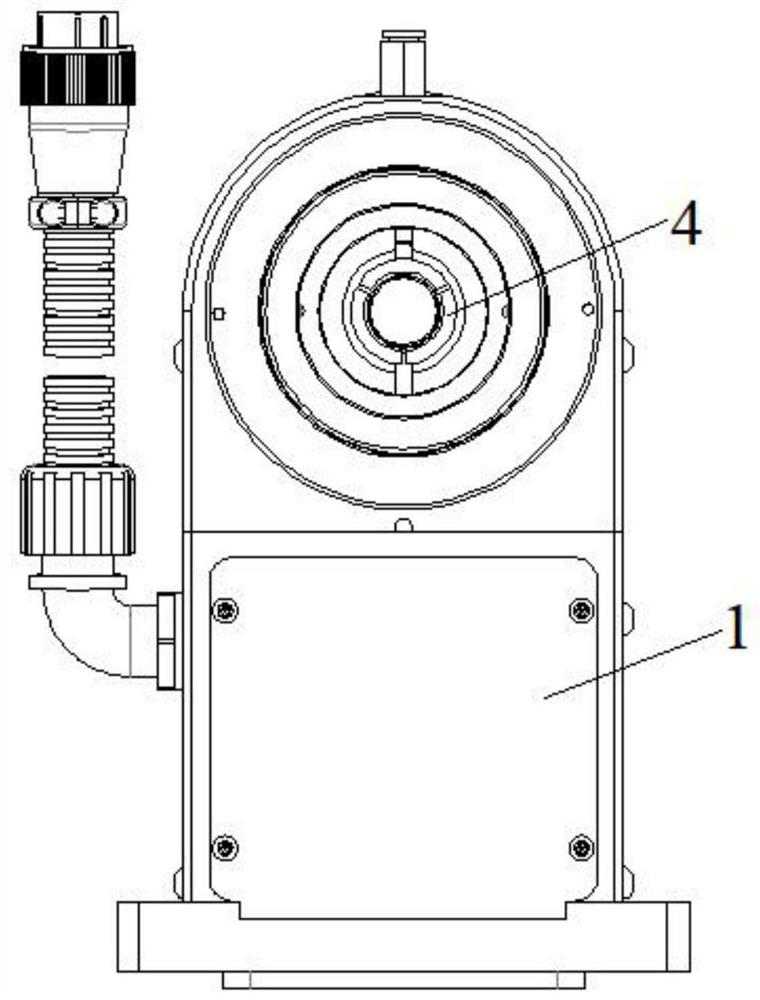
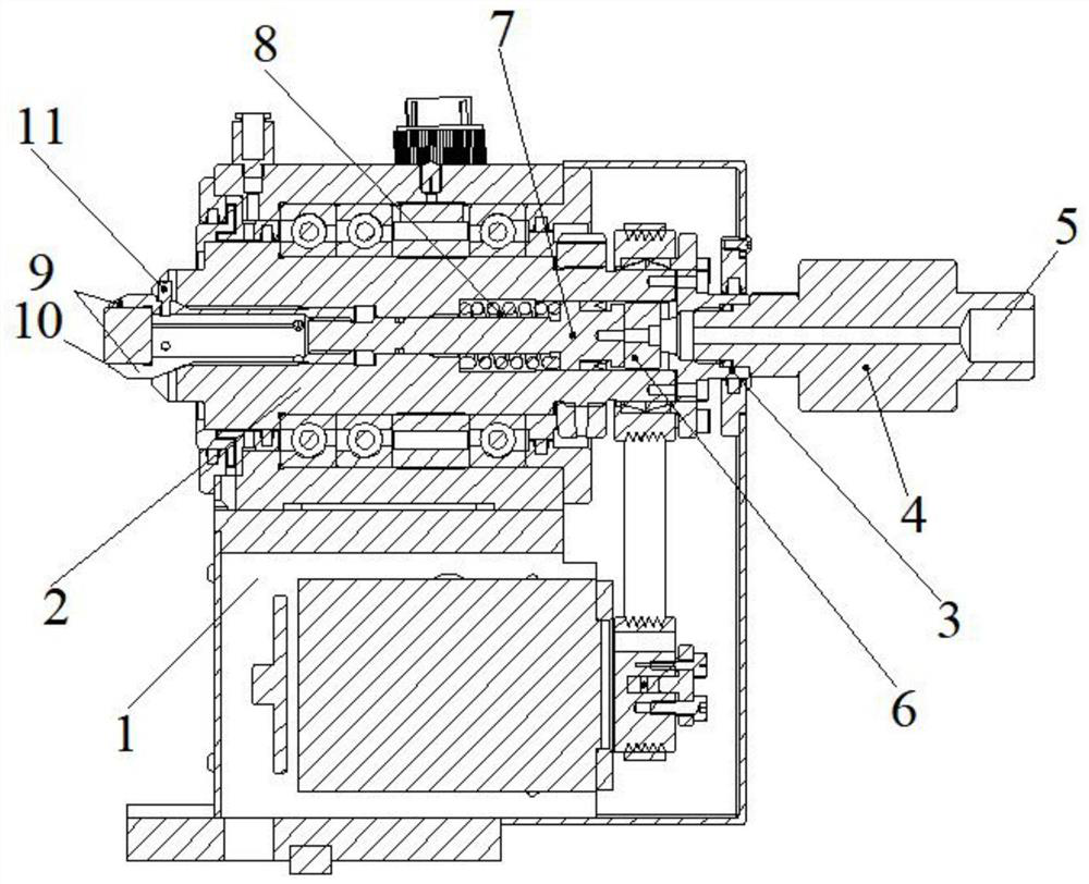
The invention provides a rotary part pneumatic tensioning device with a shaft positioning function. The rotary part pneumatic tensioning device comprises a main seat body, a workpiece rotating shaft, an oil cylinder end cover, a hydraulic oil rotating joint, an air pressure input and output port, a piston stop sliding block, a chuck pull rod piston, a chuck tensioning spring, a spring chuck and a chuck stop pin, wherein the workpiece rotating shaft is arranged in the main seat body; the workpiece rotating shaft is rotationally connected with the main seat body; one end of the workpiece rotating shaft is provided with the hydraulic oil rotating joint; the chuck pull rod piston is arranged in the workpiece rotating shaft; the piston stop sliding block is arranged at the position, located at one end of the chuck pull rod piston, in the workpiece rotating shaft; the output end of the hydraulic oil rotating joint penetrates through the piston stop sliding block and is led into one end of the chuck pull rod piston; the outer side of the chuck pull rod piston is sleeved with the chuck tensioning spring; the spring chuck is fixed at the end part of the chuck pull rod piston; a workpiece mounting position is arranged at the end part of the spring chuck; and the spring chuck is inserted into the chuck stop pin. According to the device, pneumatic tensioning of the rotary part is facilitated, and accurate and automatic clamping is facilitated.

Description

technical field [0001] The invention relates to the technical field of workpiece production equipment, in particular to a pneumatic tensioning device for rotary parts with shaft positioning. Background technique [0002] For the grinding of the chamfered part of the CBN drill bit blade for oil drilling, the existing devices mostly use chucks or spring chucks for manual clamping, which cannot realize automatic production. [0003] Therefore, it is urgent to design a pneumatic tensioning device for rotary parts with shaft positioning to solve the above-mentioned problems. SUMMARY OF THE INVENTION [0004] The purpose of the invention provided by the present invention is to provide a pneumatic tensioning device for rotary parts with shaft positioning, which is convenient for pneumatic tensioning of rotary parts and facilitates accurate automatic clamping. [0005] In order to achieve the above purpose, the present invention is achieved through the following technical solutio...

Claims


Application Information

Patent Timeline
Patent Type & Authority Applications(China)
IPC IPC(8): B24B3/24B24B41/06B24B55/00
CPCB24B3/24B24B3/247B24B55/00
Inventor 王志晟
Owner BEIJING DEMINA PRECISION MACHINERY
Why Eureka
Try Eureka