Apparatus and methods for filament crimping and manufacturing

a technology of apparatus and methods, applied in the field of crimping, can solve the problems of reducing the tensile strength or recovery properties of filament, affecting the effective crimping of sma filament wire, and affecting the manufacturing process

Active Publication Date: 2010-01-26
AUTOSPLICE SYST
View PDF35 Cites 43 Cited by
  • Summary
  • Abstract
  • Description
  • Claims
  • Application Information

AI Technical Summary

Benefits of technology

[0035]In a first aspect of the invention, a filament crimping element is disclosed. In one embodiment, the element comprises: a first plurality of cavities, the first set of cavities disposed at a spacing which creates a first plurality of features; and a second plurality of cavities, the second set of cavities disposed at a spacing which creates a second plurality of features; wherein the first and second pluralities of cavities are substantially opposite one another when the crimping element is crimped, the first plurality of features adapted to be placed at least partially within the second plurality of cavities and the second plurality of features adapted to be placed at least partially within the first plurality of cavities. In one variant, the first and second pluralities of cavities and features form a substantially serpentine channel therebetween for the filament when the crimping element is crimped. In another variant, at least one of each of the first and second pluralities of features comprises substantially rounded edges, the substantially rounded edges mitigating deformation of at least a portion of the filament during crimping.
[0036]In still another variant, the crimping element is formed from a material which has a hardness less than that of the filament, the lesser hardness of the material at least mitigating deformation of the filament by the crimping element during crimping.

Problems solved by technology

Despite the broad range of crimp technologies and implementations of SMA filaments, there has heretofore been significant difficulty in effectively crimping SMA filament wire when finer wire gauge sizes are chosen.
Specifically, prior art approaches to crimping such filaments (including use of serrations or “teeth” in the crimp surfaces) either significantly distort or damage the filament, thereby altering its mechanical characteristics in a deleterious fashion (e.g., reducing its tensile strength or recovery properties), or allowing it to slip or move within the crimp.
These problems are often exacerbated by changes in the environment (e.g., temperature, stress, etc.) of the SMA filament and crimp.
Other techniques such as brazing, soldering, and the like are also not suitable for such fine-gauge applications.
Furthermore, no suitable solution exists for maintaining a constant and uniform tensile stress on the filament during crimping.
There is, therefore, a salient unsatisfied need for an improved crimp apparatus and methods of manufacture that specifically accommodate finer gauge SMA filament wire assemblies, especially so as to maintain the desired degree of filament length control post-crimp for, inter alia, length-critical actuator applications.

Method used


Image

  • Apparatus and methods for filament crimping and manufacturing
  • Apparatus and methods for filament crimping and manufacturing
  • Apparatus and methods for filament crimping and manufacturing

Examples


Embodiment Construction

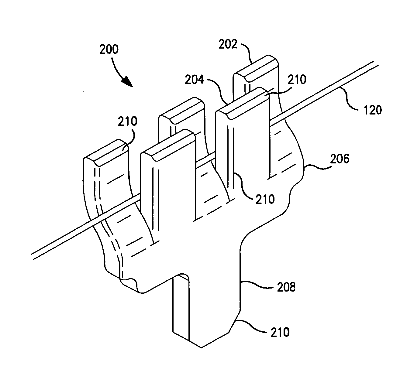
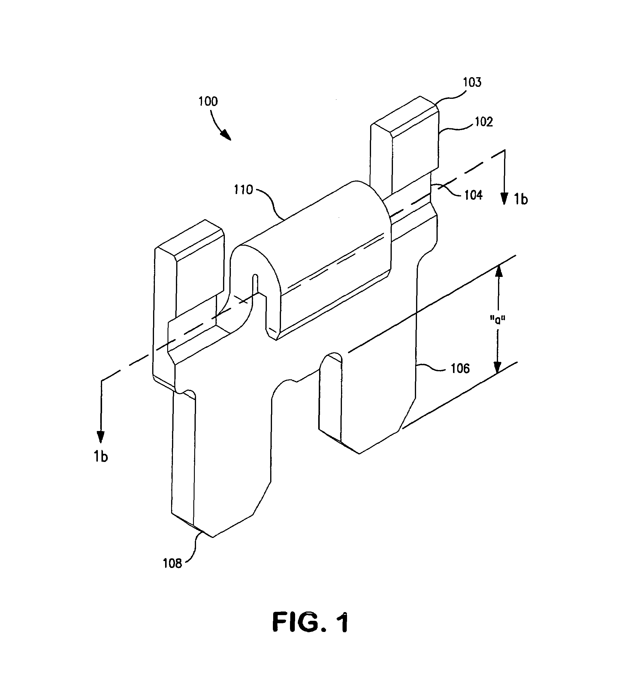
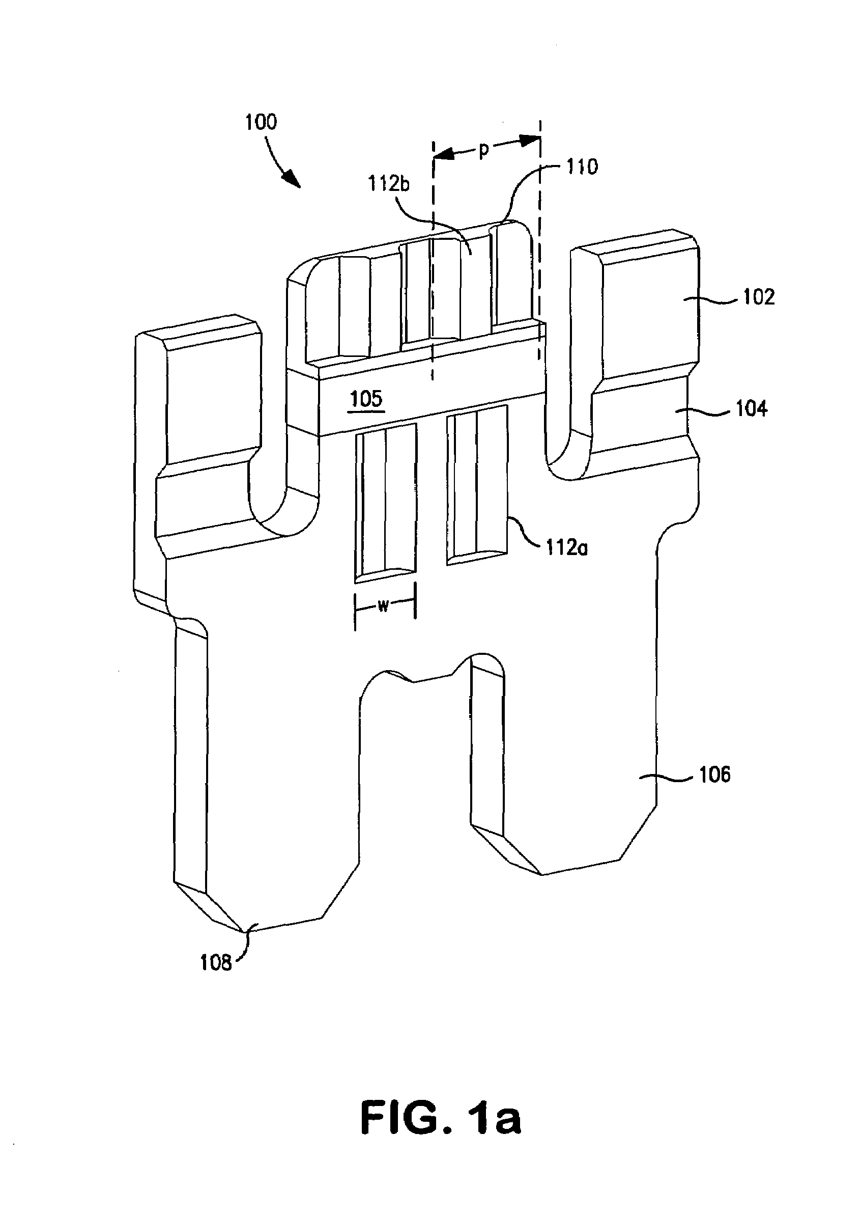
[0072]Reference is now made to the drawings wherein like numerals refer to like parts throughout.

[0073]As used herein, the term “shape memory alloy” or “SMA” shall be understood to include, but not be limited to, any metal that is capable of “remembering” or substantially reassuming a previous geometry. For example, after it is deformed, it can either substantially regain its original geometry by itself during e.g., heating (i.e., the “one-way effect”) or, at higher ambient temperatures, simply during unloading (so-called “pseudo-elasticity”). Some examples of shape memory alloys include nickel-titanium (“NiTi” or “Nitinol”) alloys and copper-zinc-aluminum alloys.

[0074]As used herein, the term “filament” refers to any substantially elongate body, form, strand, or collection of the foregoing, including without limitation drawn, extruded or stranded wires or fibers, whether metallic or otherwise.

[0075]As used herein, the term “progressive stamping” shall be understood to include any m...


PUM

PropertyMeasurementUnit
thicknessaaaaaaaaaa
sizesaaaaaaaaaa
thicknessaaaaaaaaaa

Abstract

Apparatus and methods for filament crimping. In one embodiment, the apparatus comprises a body and a filament crimp element. The filament crimp element comprises a first set of cavities disposed at a spacing which creates a first set of features and a second set of cavities disposed at a spacing which creates a second set of features. The first and second set cavities are substantially opposite one another. The first set of features are adapted to be placed at least partially within the second set of cavities and the second set of features are adapted to be placed at least partially within the first set of cavities. Methods and apparatus for the manufacture of the device are also disclosed. In addition, methods for automated placement and manufacture of assemblies using the crimp elements are also disclosed.

Description

COPYRIGHT[0001]A portion of the disclosure of this patent document contains material that is subject to copyright protection. The copyright owner has no objection to the facsimile reproduction by anyone of the patent document or the patent disclosure, as it appears in the Patent and Trademark Office patent files or records, but otherwise reserves all copyright rights whatsoever.FIELD OF THE INVENTION[0002]The present invention relates generally to the field of crimping, and in one salient aspect to fine filament crimping of, e.g., shaped memory alloy (SMA) wire.DESCRIPTION OF RELATED TECHNOLOGY[0003]The crimping of filaments such as metallic wires is well understood. Numerous techniques and configurations for wire and filament crimps are known. For example, U.S. Pat. No. 5,486,653 to Dohi issued Jan. 23, 1996 entitled “Crimp-style terminal” discloses a crimp-style terminal crimped to connect itself with an end of an electric wire includes an electric connecting part which is electri...

Claims


Application Information

Patent Timeline
Patent Type & Authority Patents(United States)
IPC IPC(8): B21F1/00
CPCH01R4/188H01R43/048H01R4/01Y10T428/1241Y10T29/49181Y10T29/5121Y10T29/49204
Inventor BOGURSKY, ROBERTFOSHANSKY, LEONIDKENNEDY, CRAIGWOOD, DARRYLSAUNDERS, MARK
Owner AUTOSPLICE SYST
Why Eureka
Try Eureka