Information processing device, organizational analysis system, computer readable medium and method
a technology of information processing and organizational analysis, applied in the field of information processing device, organizational analysis system, computer readable medium and method, can solve the problem of inability to collect accurate activity logs
- Summary
- Abstract
- Description
- Claims
- Application Information
AI Technical Summary
Benefits of technology
Problems solved by technology
Method used
Image
Examples
first exemplary embodiment
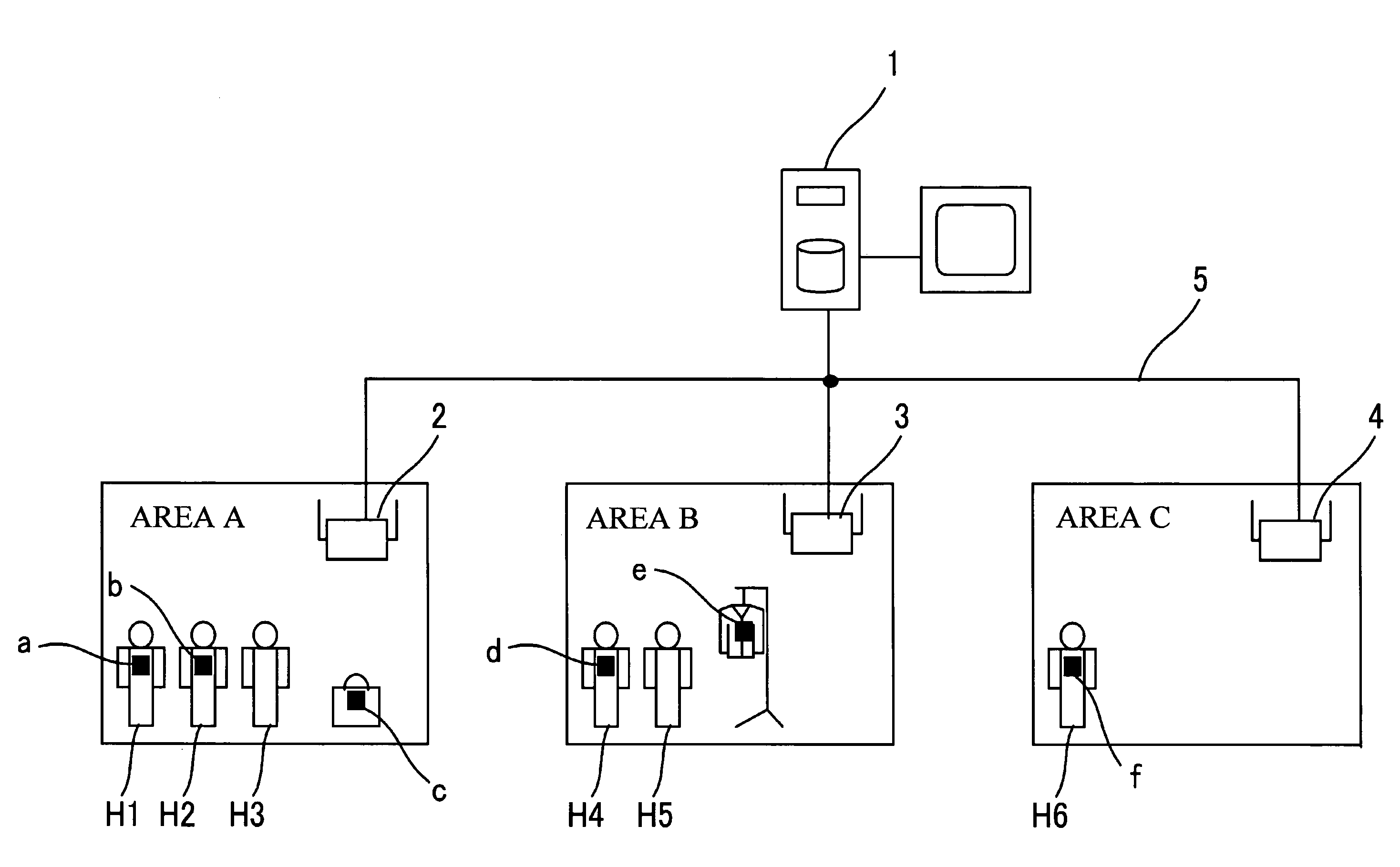
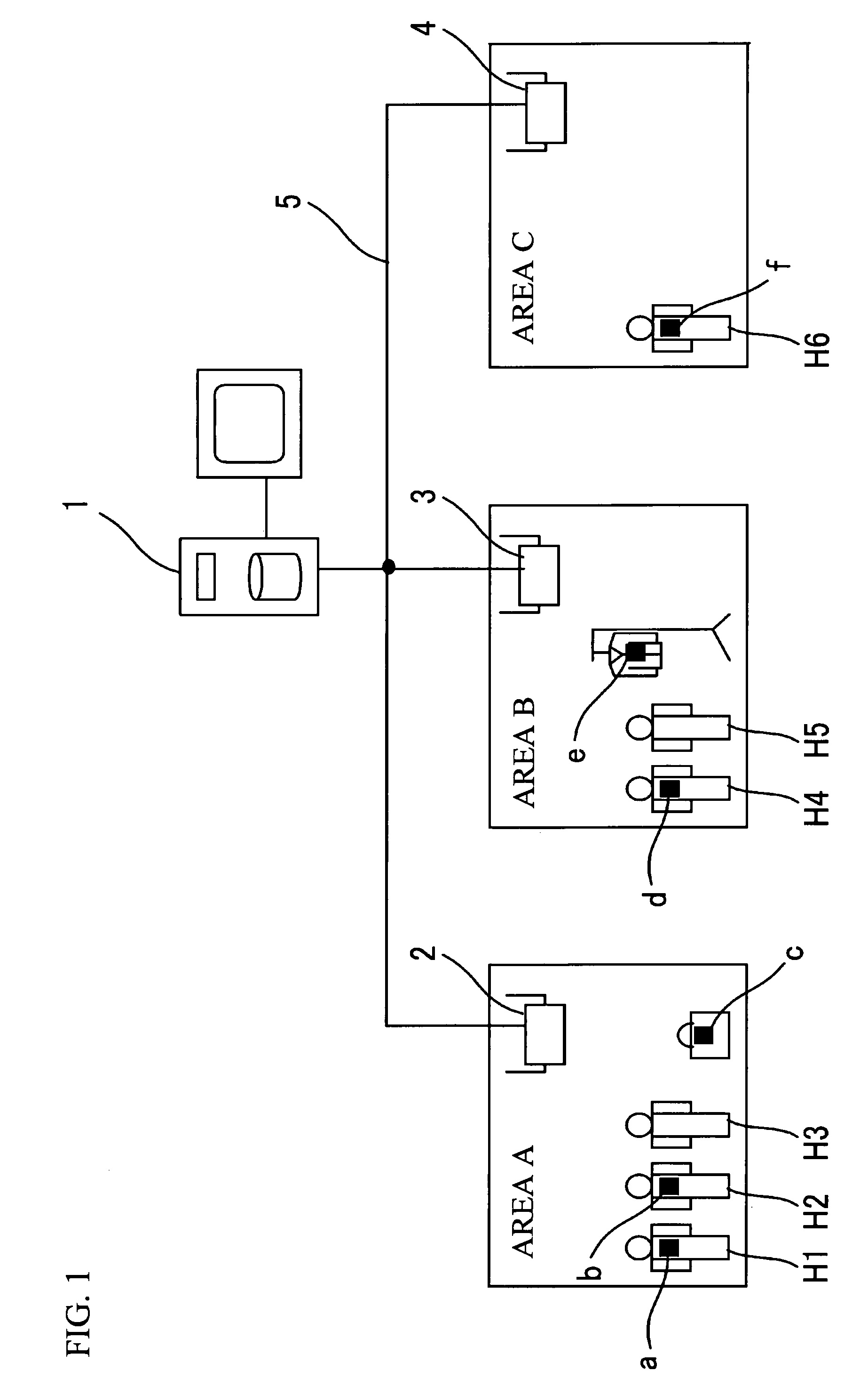
[0033]FIG. 1 illustrates the structure of an organizational analysis system that includes an information processing device in accordance with a first exemplary embodiment of the present invention. The organizational analysis system shown in FIG. 1 includes an activity log collection server 1 as an information processing device, receivers 2 through 4 that are provided in areas A through C, respectively, and active RFID tags a through f. Each active RFID tag is equipped with a battery cell and spontaneously transmits a signal.
[0034]The active RFID tags a and b are carried by persons H1 and H2 in the area A. The active RFID tag c is placed in a handbag of a person H3 in the area A. The active RFID tag d is carried by a person H4 in the area B. The active RFID tag e is in a pocket of the jacket of a person H5 in the area B. The active RFID tag f is carried by a person H6 in the area C.
[0035]The receivers 2 through 4 are connected to the activity log collection server 1 via a communicati...
second exemplary embodiment
[0064]In the first exemplary embodiment, the determination result output unit 210 outputs the results of the determinations made by the strength variance determining unit 209 determining whether the transmission device is being carried. In this exemplary embodiment, the result of the determination of whether the transmission device is being carried is stored in the history storing unit 208.
[0065]FIG. 11 is a functional block diagram of the transmission device 100 and the reception device 200. The reception device 200 of FIG. 11 is the same as the reception device 200 of FIG. 3, except that the determination result output unit 210 is removed. Also, the strength variance determining unit 209 has the function of storing the result of determination of whether the transmission device is being carried in the history storing unit 208. The other functional blocks of the reception device 200 of FIG. 11 are the same as the functional blocks of the reception device 200 of FIG. 3, and the funct...
third exemplary embodiment
[0071]In the first exemplary embodiment, the determination result output unit 210 outputs the results of determinations made by the strength variance determining unit 209 determining whether the transmission device is being carried. In this exemplary embodiment, on the other hand, the results of determinations of whether the transmission device is being carried and signals containing the tag IDs corresponding to the results are transmitted to a remote terminal.
[0072]FIG. 14 is a functional block diagram of the transmission device 100, the reception device 200, and a remote terminal 300. The reception device 200 of FIG. 14 is the same as the reception device 200 of FIG. 3, except that the determination result output unit 210 is replaced with a determination result transmitting unit 212 that transmits the results of determinations of whether the transmission device is being carried to the remote terminal 300. The other functional blocks of the reception device 200 are the same as the ...
PUM
 Abstract
Description
Claims
Application Information
 - R&D
- Intellectual Property
- Life Sciences
- Materials
- Tech Scout
- Unparalleled Data Quality
- Higher Quality Content
- 60% Fewer Hallucinations
Browse by: Latest US Patents, China's latest patents, Technical Efficacy Thesaurus, Application Domain, Technology Topic, Popular Technical Reports.
© 2025 PatSnap. All rights reserved.Legal|Privacy policy|Modern Slavery Act Transparency Statement|Sitemap|About US| Contact US: help@patsnap.com


