
Compact adjustable hinge

a technology of adjustable hinges and hinges, applied in the field of compact hinges, can solve the problems of insufficient adjustment capabilities, difficulty in installation, and prior art hinges, and achieve the effect of convenient and economical manufacture and installation

Active Publication Date: 2010-02-02
HARDWARE RESOURCES
View PDF32 Cites 24 Cited by
  • Summary
  • Abstract
  • Description
  • Claims
  • Application Information

AI Technical Summary

Benefits of technology

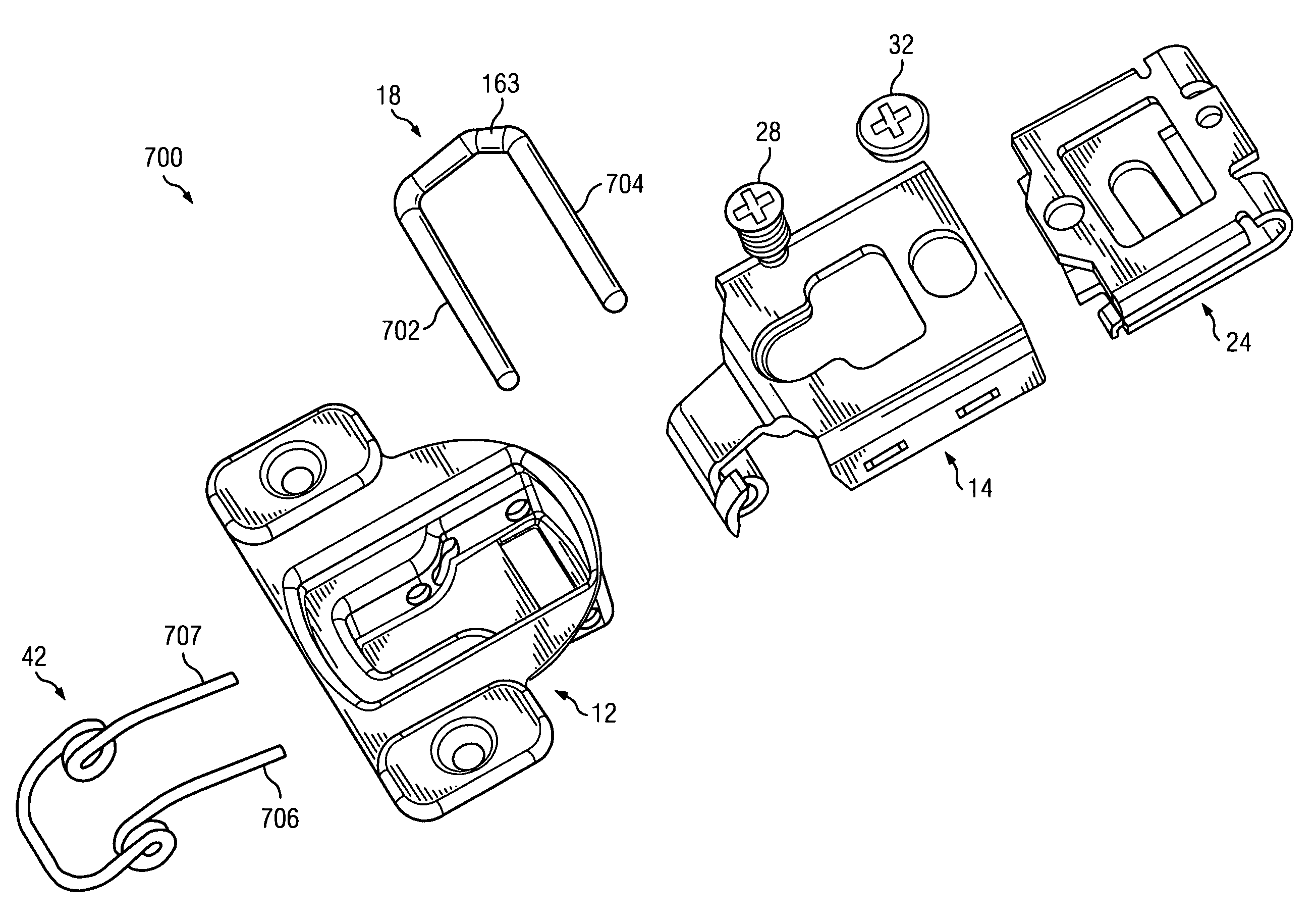
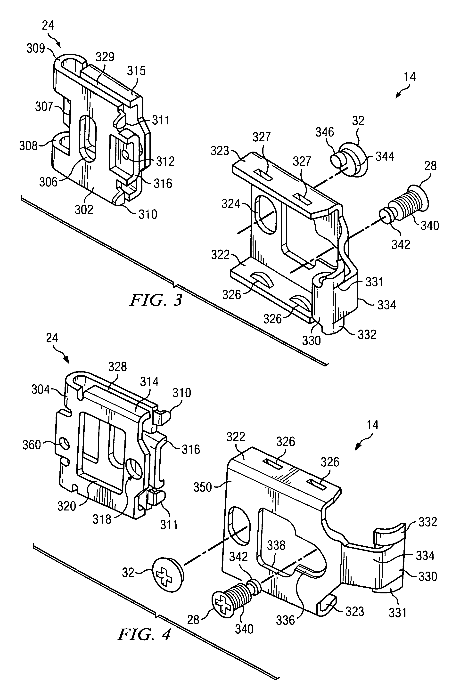
"The present invention provides an adjustable self closing compact hinge that can be easily and economically manufactured and installed. The hinge includes a cup for mounting in a door and a hinge arm assembly pivotably connected to the cup by a hinge pin. The hinge arm assembly includes a hinge arm and a fastener plate that can be adjusted in three dimensions. The fastener plate can be adjusted vertically and horizontally through an eccentric cam. The hinge is simple in design and requires fewer component parts, making it more efficient and cost-effective."

Problems solved by technology

Prior art hinges suffer from various disadvantages including difficulty in installation, insufficient adjustment capabilities, instability of the adjustments made, complicated construction, and high manufacturing costs.
In order to accomplish adjustments in three dimensions, this device requires a complicated assembly necessitating several assembly connection points.
All of the above increases the manufacturing complexity and cost of the device.
The device of the '567 patent also requires multiple intricate and expensive pieces requiring complex assembly steps and hardware to function as an adjustable hinge.
After repeated adjustment as is required to secure and adjust a door, the fit of newly inserted screws becomes unstable which ultimately results in an insecure mounting of the door on the cabinet.

Method used


Image

  • Compact adjustable hinge
  • Compact adjustable hinge
  • Compact adjustable hinge

Examples


Embodiment Construction

[0022]In the descriptions that follow, like parts are marked throughout the specification and drawings with the same numerals. The drawing figures are not necessarily drawn to scale and certain figures may be shown in exaggerated or generalized form in the interest of clarity and conciseness. Copyright protection is claimed to the extent that protection is provided by copyright law.

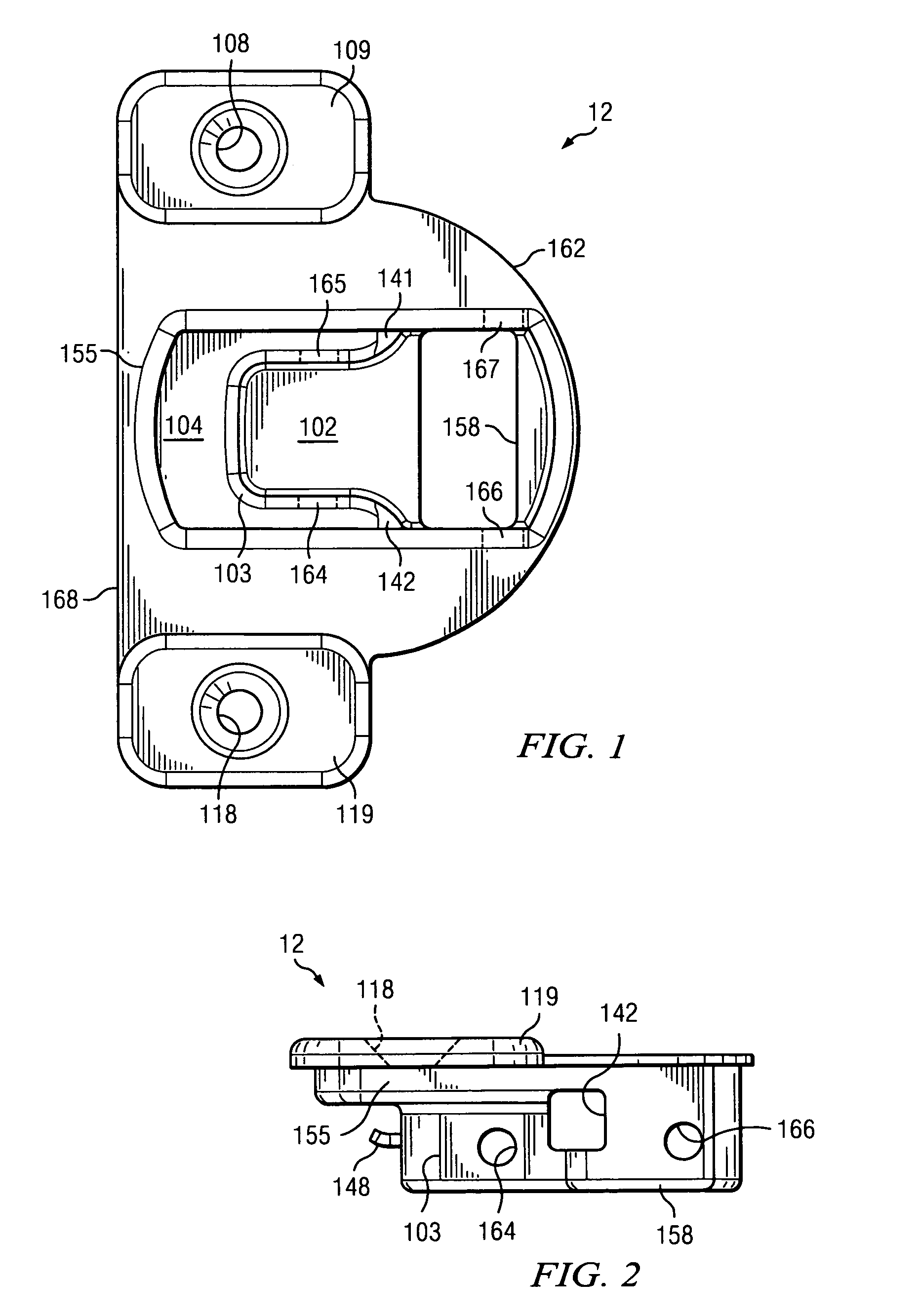
[0023]Hinge cup 12 is shown in FIGS. 1 and 2. Hinge cup 12 has a semicircular shaped brim 162 opposite ledge 168 encompassing a generally rectangular shaped indention or cup. Ledge 168 connects support 109 and support 119. Support 109 defines a circular support hole 108 and support 119 defines a circular support hole 118. The indention or cup of hinge cup 12 includes two different horizontal surfaces, cup floor 102 and cup shelf 104. Cup floor 102 forms the base of the cup shape and includes a generally rectangular shaped aperture floor hole 158. Cup shelf 104 is generally a “horseshoe shaped” horizontal ...


PUM


Abstract

The invention disclosed provides a compact hinge capable of a vertical, a horizontal, and an overlay adjustment, comprised of a cup portion and a hinge arm with one end pivotably connected to the cup portion and the other end slideably connected to a fastener plate. The fastener plate further comprises a first semi-planar surface for contact with a cabinet frame and a second semi-planar surface for slideable engagement with the hinge arm to accomplish the horizontal adjustment. The first and second semi-planar surfaces are interconnected by a deformable hinge section that allows for an elastically resilient connection at one end and an adjusting screw at the other end for a horizontally arcing movement relative to each resulting in an overlay adjustment. The fastener plate further comprises an elongated aperture in the first semi-planar surface through which the vertical adjustment is accomplished.

Description

FIELD OF THE INVENTION[0001]The present invention relates to a compact hinge for furniture products. In particular, the present invention relates to a compact overlay hinge that is capable of adjustment in three dimensions.BACKGROUND OF THE INVENTION[0002]Cabinet doors for cabinets generally must be individually adjusted to compensate for manufacturing tolerances. Adjustment is usually required in more than one dimension. If the door has two or more hinges, as is usually the case, adjustments must be carried out on each hinge with respect to the other hinges. A “vertical adjustment” is required when the door does not seat properly with respect to the top and bottom of the cabinet frame. An “overlay adjustment” is a lateral or “side to side” adjustment required when the door does not properly align with the sides of the cabinet frame. A horizontal or an “in and out” adjustment required when the door does not lay flush with the cabinet frame.[0003]Prior art hinges suffer from various ...

Claims


Application Information

Patent Timeline
Patent Type & Authority Patents(United States)
IPC IPC(8): E05D7/04
CPCE05D7/0407Y10T16/53253Y10T16/53225E05Y2900/20
Inventor LOWE, MARK JEFFREYNALLAMOTTU, UDHAYA BHASKAR
Owner HARDWARE RESOURCES
Learn More